Wednesday, January 30, 2008
Saturday, January 26, 2008
Current Developments
INTRODUCTION
Just a quick note to keep you all informed on the current goings-on related to this site and its content.
IMINT & ANALYSIS FEATURED IN JANE'S
As online subscribers have no doubt discovered, Jane's Missiles & Rockets has two articles in their February print edition featuring the work of this website. In "Iran may have lined up S-300 SAM systems", my work detailing Iran's air defense network is discussed. "China deploys KS-1A SAM" is a report detailing my discovery of the first KS-1A SAM site in China, featured first on this blog a month ago. Hopefully I can contribute more to Jane's and other industry-related publications in the future.
FORTHCOMING PROJECTS
The next three articles for this site are being prepared, and they are going to take a little bit of time, so bear with me. The most extensive is going to be an analysis of China's air defense network, with a good deal of future projection mixed in. Special attention will be given to air defenses along the Taiwan Strait. The other two articles are going to be a feature on Russian space surveillance facilities (inspired by my recent discovery of the Far East Krona site in Google Earth) and an analysis of the impact of the S-300PT in Iranian service.
SAM SITE PROJECTS
The SAM Site .kmz file for Google Earth is still updated on a regular basis whenever I have enough new locations to warrant uploading a new file. I am also looking at developing a document based on that data, something along the lines of a guide to worldwide SAM systems broken down by nation, and featuring location data and information on the numbers and types of individual components at each location.
THE S-300P
I am still preparing what should be the definitive look at the S-300P SAM system, to replace an earlier article on this site, as well as numerous other things. Smaller-scope articles will still be posted as time permits, but my current primary focus is on the Chinese article, so bear with me if the site appears stagnant for a week or so.
CONCLUSION
As always, comments are welcome and encouraged. I'd encourage visitors to post a comment to this thread to suggest ideas for future articles as well.
Saturday, January 12, 2008
China's J-10: An Imagery Analysis
INTRODUCTION
The most important modernisation program underway within China's PLAAF is the introduction of the Chengdu J-10 into widespread service. The J-10 is a modern, 4th generation fighter aircraft combining a canard-delta layout with modern avionics and a BVR air-to-air weapon system. Careful analysis of current and past open-source overhead imagery has provided a detailed look at the current status of the J-10 program insofar as operational deployment is concerned. This highlights the value of overhead imagery as an analysis tool, as the J-10 program was not even officially acknowledged by the Chinese military until late 2006. Such secrecy is common in China, and goes a long way towards discrediting the various designs purported to represent the next-generation XXJ, which were revealed as far back as 2002. The fact that China refused to acknowledge an aircraft already visible in hundreds of photographs but at the same time was releasing images of the designs competing for a new stealthy fighter program would seem to be an obvious contradiction in policy, but that is another issue entirely.
TEST FACILITIES
Chengdu
Chengdu Aircraft Corporation (CAC) is the manufacturer of the J-10 fighter aircraft. Many of the early flight tests took place from Chengdu's facility located northwest of Chengdu in central China. Many of the prototypes are still located at the CAC facility and continue to serve various purposes in the continued development of the J-10.
The following image depicts the J-10 area at CAC's flight test facility:

Xian-Yanliang
Xian-Yanliang is home to the Chinese Flight Test Establishment, or CFTE. The CFTE handles the bulk of the flight test programs for the PLAAF, and as such evaluated the J-10 extensively. Xian-Yanliang is located to the northeast of Xian in central China.
The following image depicts a J-10 on the ramp at the CFTE facility:

Dingxin AB
Dingxin airbase, located in north central China near the Shuangchengzi missile test range, is home to a great deal of PLAAF flight test efforts. Pockmarked terrain and targets marked in the desert indicate that among other things, Dingxin is home to weapons integration testing. As such, J-10s have deployed to Dingxin on various occasions beginning in 2002 to conduct trials of the weapon system, including integration of the PL-12 ARH MRAAM.
The following image depicts a lineup of six J-10s on the ramp at Dingxin:

Imagery available in October of 2006 depicted three J-10s on the ramp at Dingxin, with one of the aircraft participating in an apparent display lineup for government or military officials, as seen in the images below:


Cangzhou AB and Jiugucheng AB
J-10s are visible in residence at two airbases known to be subordinate to the Chinese Flight Test & Training Center (FTTC). The FTTC is based at Cangzhou AB south of Beijing. It has been reported that between six and ten J-10s were delivered to Cangzhou in March of 2003 to form the 13th Operational Trials Regiment. Recent imagery taken from 2006 and 2007, however, suggests that six aircraft were delivered to Jiugucheng AB further south, a location also associated with the FTTC in some sources. This does not indicate that no J-10s were operated or are currently operated from Cangzhou AB, but as no J-10s are visible in available imagery of Cangzhou AB one can only speculate as to the status of any J-10 unit at that location.
At least three J-10s are still visible on the ramp at Jiugucheng AB, with six shelters having been constructed for housing the new fighters. The following two images illustrate the alteration of the ramp area. The first image depicts three J-10s sitting behind three of the four hangars, while the second image illustrates the fact that at least two more hangars have been constructed for the J-10s in residence, with a further eight hangars having been constructed for additional aircraft:


If the J-10 Operational Trials Regiment was in fact based at Cangzhou AB, it is possible that the unit based at Jiugucheng is the operational conversion unit tasked with pilot training for J-10 crews. Conversely, the opposite may be true; the OTR may have been based at Jiugucheng AB, with the larger 10 aircraft OCU being located at Cangzhou AB. Whatever the case may be, it is obvious that the J-10 has operated at some point in the past from Jiugucheng AB in some capacity, and the construction of the new hangar spaces does seem to indicate a more permanent presence than an Operational Trials Regiment, whose aircraft may have been reapportioned to operational units following the certicifation of the J-10 for operational service in 2004.
OPERATIONAL UNITS
Liuliang AB
The first operational J-10 unit was the 131st Air Regiment of the 44th Fighter Division. This unit formed between July and August of 2004.
The following image depicts the 28 shelters for the J-10s based at Liuliang AB, as seen in photographs of the PLAAF induction ceremony:

Changxing AB
The second operational J-10 unit formed in early 2006 at Changxing AB near Shanghai.
The following image depicts the 28 shelters for the J-10s based at Changxing AB, as well as a solitary J-10 parked on the open ramp:

Siuxi AB
The most recent J-10 unit known to have been formed became operational in 2007 at Siuxi AB, located in southern China north of Hainan Island. Currently available imagery is outdated and does not yet indicate any evidence of J-10 operations from this location.
CURRENT INVENTORY
The following image illustrates the current airbases where J-10s are known to operate or have operated in the past, as described above:

Analysis of the hangar spaces at Liuliang and Changxing air bases indicates that an operational J-10 regiment would consist of no fewer than 28 aircraft. Discounting test aircraft and accounting for the fact that the 4th Air Regiment is known to be operating out of Siuxi AB despite the fact that currently available imagery does not depict any newly constructed hangars for the J-10 unit, there should be no less than 84 J-10s between the three operational units, provided that they are all at full strength. There are also up to 16 other trials aircraft spread between Jiugucheng and Cangzhou airbases, indicating that over 100 J-10s may have been produced to date when the various flight test articles held by Chengdu are accounted for.
The next J-10 unit to enter operational service will most likely be found in either the Nanjing or Guangzhou Military Region. Found across the strait from Formosa, the presence of a J-10 unit in this geographical region would fill a current gap between Changxing and Siuxi airbases.
CONCLUSION
Replacing the large numbers of J-7s with the new J-10 is a top priority for the PLAAF. The J-10 is by far the most advanced aircraft yet to be produced by the Chinese military aviation complex, and as such will enable the PLAAF to be far more effective in a modern air combat environment. With hundreds of FLANKER-family aircraft already in service, and up to 300 J-10s projected to be produced, the PLAAF is rapidly becoming one of the more modern and well equipped air arms in the world, a welcome change from as recently as ten years ago when FLANKERs were scarce, and aged designs like the J-7 and J-8 were relied upon to provide the bulk of the Chinese air combat force.
SOURCES
-All overhead imagery provided courtesy of Google Earth.
Scramble
Sinodefence
Chinese Military Aviation
Effective Searching in Google Earth
INTRODUCTION
I am often asked about the time and effort it takes to peruse through Google Earth's high resolution imagery to locate various items, most often SAM sites, of which I have catalogued over 1400. Locating military installations and other interesting objects can be a time consuming endeavor, but it can be made far easier with a few simple techniques. In this article I will share some of those techniques which have served me well in the past, with the hope that your experience viewing imagery through such sources as Google Earth will be that much more enjoyable and interesting.
COMPUTER SETTINGS
To begin, we will exmamine some of the basic computer settings that are helpful in examining imagery. My monitor is a widescreen display with a resolution of 1920 x 1200 pixels. Setting your screen to the maximum resolution is helpful when viewing imagery sources as it aids in bringing out some of the fine detail that can be seen. Inside the Google Earth options menu, set the Detail Area to the maximum setting of 1024 x 1024. Even with a widescreen monitor, with the Placemark and Layer tabs expanded on the left of the screen the entire imagery display will then display eitirely in full detail, without any of the areas surrounding the very center of the image being blurred. This will greatly aid in examining what you see before you on your monitor.
BEGINNING EXAMINATION
In the bottom right of the imagery display area in Google Earth, you will notice a label called "Eye alt", followed by a series of numbers and an abbreviation. What these numbers are telling you is the alttude, in either feet or miles, that you are viewing the image from. I have found that the optimal viewing altitude for quick perusal of a given area is 15,000 feet.
When imagery is added into Google Earth, it is usually in the form of strips of either satellite or aerial imagery. These strips are in reality collections of square-shaped images that have been combined together into a mosaic. With my monitor settings, each individual square can be broken up into six rows, with each row being approximately three and a half screens across. Each section can then be examined relatively quickly, by viewing each screen one at a time until each section of imagery has been analysed.
The following graphic illustrates this concept. Notice that coordinates are provided where a single square of imagery can be examined in this fashion, making it easier for you to determine the dimensions of the area based on your own computer's monitor settings.
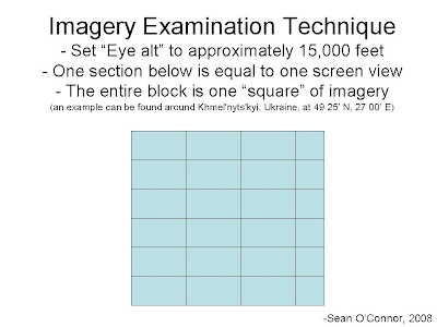
The key here is to keep an eye out for new areas of high-resolution coverage to examine. When I started my SAM site file, there was very little high-resolution imagery outside of the United States and Western Europe. I kept abreast of imagery updates to Google Earth through the Google Earth Blog, found here. Each time a new area appeared, I went through it to see what I could find.
It should also be noted that "Eye alt" is completely unrelated to the altitude of the terrain found in the lower left corner, denoted by "elev" for elevation. Regardless of the terrain's elevation, your "Eye alt" should be at 15,000 feet. This will give you the same viewpoint at all times. Setting the elevation to 15,000 feet can result in some issues, especially when the terrain is elevated around 5 or 10 thousand feet. You will end up with a much closer viewpoint and have to spend a lot longer examining a given area.
THE HUNT IS ON
Once you have found a pattern for examining an area of imagery, the trick is to find items of interest to tag for identification. There are two ways to do this.
The first method of identifying interesting locations is to simply create a folder and insert a placemark where something of interest may be located. These items can then be revisited later once the area has been thoroughly examined. Close-up inspection will often divulge the identity of the structure or facility.
The second method requires a little more time and patience, and a degree of knowledge. I have been examining SAM sites, for example, for quite some time now. I personally find it easier to immediately identify the sites to save myself the trouble of having to reexamine them and rename the placemarks. Some sites, like those of SA-1 or SA-5 systems, can be readily identified even from 15,000 feet, but others may have to be zoomed in on to clarify their type. The problem here is that you have to be careful when zooming back out to keep your screen centered on the same location it was before you zoomed in. This allows you to avoid skipping something potentially interesting because you reset your screen to a new area when you zoomed back out.
Finding something that looks interesting is a relatively simple task from a 15,000 foot vantage point. Consider the image below. It was screen captured from an altitude of approximately 15,000 feet in Belarus. Residential areas, fields, and forests can be seen, as well as a number of roads. Two facilities in the center of the image stand out immediately. They do so because they are markedly different from their surroundings, seeming "out of place" in a rural area. The northern facility is clearly rectangular and isolated from the surrounding areas, while the southern area has been cleared out from a patch of trees in an interesting pattern. As it turns out, the northern facility houses the 64N6 search radar for the S-300PMU SAM battery in the southern facility.
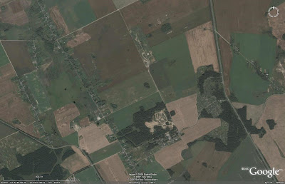
The simple rule here is to merely see if anything catches your eye. You may end up locating a power plant or a factory, but this can be determined later when you closely examine your finds. With a little bit of experience you will gain a feel for the types of sites and objects that you are looking for and will be able to pick them out of their surroundings with greater ease.
IDENTIFYING OBJECTS
Locating something is only half of the equation. The next step is to identify what you are looking at. There are many ways to do this.
First, the simplest method of identifying something is to see if someone else has done the work for you! In the layers tab of Google Earth, expand the "Gallery" menu and click on the "Google Earth Community" box. This will insert any placemarks that Google Earth users have uploaded into the server. If your location has already been examined, chances are it has a placemark attached to it, which you can then view in Google Earth, and copy into your own file if you desire. This does have an advantage, as you then have a baseline for comparing other items you find if a like item has already been marked. Do take note that the accuracy of placemarks in Google Earth is not guaranteed, however.
The alternative is to identify the locations yourself. This can be a very time consuming endeavor. To be frank, in order to do this effectively, it does help a great deal to have some knowledge about what you are trying to identify. This knowledge can come from personal experience, or from external sources. If you are trying to identify a SAM system, for example, a publication such as Jane's Land Based Air Defence can be of great value. While Jane's does not provide any detail regarding site layouts, it does provide you with some useful information. There are pictures of most of the relevant equipment, for example. It takes a bit of thought to equate a side-on photograph to a piece of top-down imagery, but it can be done. The dimensions provided are very valuable, as they give you a yardstick to compare your finding to. If you are examining a SAM site, for example, and you have determined that the launch rails should be 30 feet long, any potential matches can be measured in Google Earth using the ruler tool found at the top of the screen (do take care to chage the unit of measurement to whatever you have found; if you have been given a length in meters, for example, make sure you aren't measuring in feet!). If you find a number of objects that are 20 feet long, then you are obviously not looking at that particular SAM system. Jane's also provides a list of users for each SAM system. A list of nations associated with what it is you are hunting for can save you a lot of time. For example, according to Jane's the nation of Brazil has no SAM systems identifiable in Google Earth imagery (i.e. large, static SAM sites, not man-portable units or those mounted on small, unidentifable vehicles). That saved me from having to take the time out to examine all of the imagery in Brazil. Organizing your search in a fashion similar to this will make it a lot easier as you won't get frustrated searching for and not finding things in places that they have no business being in the first place!
To be blunt, successfully identifying objects will take some practice, but once you have become proficient it is a much smoother process. It all boils down to the amount of effort you put into the process.
OTHER TRICKS
There are some other tricks to identifying objects in Google Earth.
If you are looking for facilities in a given area, you might do well to locate a map with the facilities marked. Maps can be inserted into Google Earth as Overlays. Overlays place objects such as photographs or maps over the visible imagery. Their transparency can be adjusted so that you can view the imagery through the map. Overlays can be tricky to insert. You have to be careful to match the map to the imagery, and that can take some time to get right. Otherwise, the locations on the map will not match up with the imagery, and the map will be of no help whatsoever.
I used an overlay map to aid in identifying the inner and outer SA-1 SAM rings around Moscow. To do this, I located a map of the SA-1 locations in the CIA's FOIA archives available on the web. The map can be seen below:
Once I had matched the map up with the imagery, I simply adjusted the transparency factor and browsed the area. Fortunately, SA-1 sites are enormous and were easily identifiable even in low-resolution areas, and I had all of them mapped out in short order.
Another technique is to locate an external source of locations far less irritating than something requiring the creation of an overlay. One fine example is Google Earth user LeX2's website depicting SA-5 SAM sites, found here. By zooming in on his map, I was able to then extrapolate the locations of the facilities by searching the same areas in Google Earth. At one point, we had both been identifying SAM sites for a while, and as he had concentrated on SA-5 sites, he inquired about incorporating his sites into my SAM catalog. I enthusiastically agreed, as it would save me the time of finding them myself, and he had located numerous sites in low resolution areas that I would normally not have concentrated on anyway.
This brings us to the third trick, the Google Earth Community, found here. By joining the community, you can post findings on the forum which will eventually be entered into the server to be viewed by everyone in Google Earth. The benefits of this community are sections dedicated for like-minded individuals, such as those of us who primarily hunt down military objects. There is a substantial knowledge base there, and chances are that someone will be able to help you identify something that has you stumped. My SAM site project began at the community as a file containing the aforementioned SA-1 rings, and through the interaction with and encouragement from users there has evolved into the 1400+ site database that it is today.
CONCLUSION
To sum up, the steps for successfully browsing and identifying objects are as follows: set your viewing altitude to 15,000 feet, break the area up into portions denoted by the area encapsulated by the viewing area on your screen, and move piece by piece through a given piece of imagery, marking down the locations of interesting items as you progress. Who knows what you may find! Keep in mind that this is can be very time consuming, however, and may end up with you creating your own blog!
SOURCES
-Satellite imagery of Belarus provided courtesy of Google Earth.
I am often asked about the time and effort it takes to peruse through Google Earth's high resolution imagery to locate various items, most often SAM sites, of which I have catalogued over 1400. Locating military installations and other interesting objects can be a time consuming endeavor, but it can be made far easier with a few simple techniques. In this article I will share some of those techniques which have served me well in the past, with the hope that your experience viewing imagery through such sources as Google Earth will be that much more enjoyable and interesting.
COMPUTER SETTINGS
To begin, we will exmamine some of the basic computer settings that are helpful in examining imagery. My monitor is a widescreen display with a resolution of 1920 x 1200 pixels. Setting your screen to the maximum resolution is helpful when viewing imagery sources as it aids in bringing out some of the fine detail that can be seen. Inside the Google Earth options menu, set the Detail Area to the maximum setting of 1024 x 1024. Even with a widescreen monitor, with the Placemark and Layer tabs expanded on the left of the screen the entire imagery display will then display eitirely in full detail, without any of the areas surrounding the very center of the image being blurred. This will greatly aid in examining what you see before you on your monitor.
BEGINNING EXAMINATION
In the bottom right of the imagery display area in Google Earth, you will notice a label called "Eye alt", followed by a series of numbers and an abbreviation. What these numbers are telling you is the alttude, in either feet or miles, that you are viewing the image from. I have found that the optimal viewing altitude for quick perusal of a given area is 15,000 feet.
When imagery is added into Google Earth, it is usually in the form of strips of either satellite or aerial imagery. These strips are in reality collections of square-shaped images that have been combined together into a mosaic. With my monitor settings, each individual square can be broken up into six rows, with each row being approximately three and a half screens across. Each section can then be examined relatively quickly, by viewing each screen one at a time until each section of imagery has been analysed.
The following graphic illustrates this concept. Notice that coordinates are provided where a single square of imagery can be examined in this fashion, making it easier for you to determine the dimensions of the area based on your own computer's monitor settings.

The key here is to keep an eye out for new areas of high-resolution coverage to examine. When I started my SAM site file, there was very little high-resolution imagery outside of the United States and Western Europe. I kept abreast of imagery updates to Google Earth through the Google Earth Blog, found here. Each time a new area appeared, I went through it to see what I could find.
It should also be noted that "Eye alt" is completely unrelated to the altitude of the terrain found in the lower left corner, denoted by "elev" for elevation. Regardless of the terrain's elevation, your "Eye alt" should be at 15,000 feet. This will give you the same viewpoint at all times. Setting the elevation to 15,000 feet can result in some issues, especially when the terrain is elevated around 5 or 10 thousand feet. You will end up with a much closer viewpoint and have to spend a lot longer examining a given area.
THE HUNT IS ON
Once you have found a pattern for examining an area of imagery, the trick is to find items of interest to tag for identification. There are two ways to do this.
The first method of identifying interesting locations is to simply create a folder and insert a placemark where something of interest may be located. These items can then be revisited later once the area has been thoroughly examined. Close-up inspection will often divulge the identity of the structure or facility.
The second method requires a little more time and patience, and a degree of knowledge. I have been examining SAM sites, for example, for quite some time now. I personally find it easier to immediately identify the sites to save myself the trouble of having to reexamine them and rename the placemarks. Some sites, like those of SA-1 or SA-5 systems, can be readily identified even from 15,000 feet, but others may have to be zoomed in on to clarify their type. The problem here is that you have to be careful when zooming back out to keep your screen centered on the same location it was before you zoomed in. This allows you to avoid skipping something potentially interesting because you reset your screen to a new area when you zoomed back out.
Finding something that looks interesting is a relatively simple task from a 15,000 foot vantage point. Consider the image below. It was screen captured from an altitude of approximately 15,000 feet in Belarus. Residential areas, fields, and forests can be seen, as well as a number of roads. Two facilities in the center of the image stand out immediately. They do so because they are markedly different from their surroundings, seeming "out of place" in a rural area. The northern facility is clearly rectangular and isolated from the surrounding areas, while the southern area has been cleared out from a patch of trees in an interesting pattern. As it turns out, the northern facility houses the 64N6 search radar for the S-300PMU SAM battery in the southern facility.

The simple rule here is to merely see if anything catches your eye. You may end up locating a power plant or a factory, but this can be determined later when you closely examine your finds. With a little bit of experience you will gain a feel for the types of sites and objects that you are looking for and will be able to pick them out of their surroundings with greater ease.
IDENTIFYING OBJECTS
Locating something is only half of the equation. The next step is to identify what you are looking at. There are many ways to do this.
First, the simplest method of identifying something is to see if someone else has done the work for you! In the layers tab of Google Earth, expand the "Gallery" menu and click on the "Google Earth Community" box. This will insert any placemarks that Google Earth users have uploaded into the server. If your location has already been examined, chances are it has a placemark attached to it, which you can then view in Google Earth, and copy into your own file if you desire. This does have an advantage, as you then have a baseline for comparing other items you find if a like item has already been marked. Do take note that the accuracy of placemarks in Google Earth is not guaranteed, however.
The alternative is to identify the locations yourself. This can be a very time consuming endeavor. To be frank, in order to do this effectively, it does help a great deal to have some knowledge about what you are trying to identify. This knowledge can come from personal experience, or from external sources. If you are trying to identify a SAM system, for example, a publication such as Jane's Land Based Air Defence can be of great value. While Jane's does not provide any detail regarding site layouts, it does provide you with some useful information. There are pictures of most of the relevant equipment, for example. It takes a bit of thought to equate a side-on photograph to a piece of top-down imagery, but it can be done. The dimensions provided are very valuable, as they give you a yardstick to compare your finding to. If you are examining a SAM site, for example, and you have determined that the launch rails should be 30 feet long, any potential matches can be measured in Google Earth using the ruler tool found at the top of the screen (do take care to chage the unit of measurement to whatever you have found; if you have been given a length in meters, for example, make sure you aren't measuring in feet!). If you find a number of objects that are 20 feet long, then you are obviously not looking at that particular SAM system. Jane's also provides a list of users for each SAM system. A list of nations associated with what it is you are hunting for can save you a lot of time. For example, according to Jane's the nation of Brazil has no SAM systems identifiable in Google Earth imagery (i.e. large, static SAM sites, not man-portable units or those mounted on small, unidentifable vehicles). That saved me from having to take the time out to examine all of the imagery in Brazil. Organizing your search in a fashion similar to this will make it a lot easier as you won't get frustrated searching for and not finding things in places that they have no business being in the first place!
To be blunt, successfully identifying objects will take some practice, but once you have become proficient it is a much smoother process. It all boils down to the amount of effort you put into the process.
OTHER TRICKS
There are some other tricks to identifying objects in Google Earth.
If you are looking for facilities in a given area, you might do well to locate a map with the facilities marked. Maps can be inserted into Google Earth as Overlays. Overlays place objects such as photographs or maps over the visible imagery. Their transparency can be adjusted so that you can view the imagery through the map. Overlays can be tricky to insert. You have to be careful to match the map to the imagery, and that can take some time to get right. Otherwise, the locations on the map will not match up with the imagery, and the map will be of no help whatsoever.
I used an overlay map to aid in identifying the inner and outer SA-1 SAM rings around Moscow. To do this, I located a map of the SA-1 locations in the CIA's FOIA archives available on the web. The map can be seen below:

Once I had matched the map up with the imagery, I simply adjusted the transparency factor and browsed the area. Fortunately, SA-1 sites are enormous and were easily identifiable even in low-resolution areas, and I had all of them mapped out in short order.
Another technique is to locate an external source of locations far less irritating than something requiring the creation of an overlay. One fine example is Google Earth user LeX2's website depicting SA-5 SAM sites, found here. By zooming in on his map, I was able to then extrapolate the locations of the facilities by searching the same areas in Google Earth. At one point, we had both been identifying SAM sites for a while, and as he had concentrated on SA-5 sites, he inquired about incorporating his sites into my SAM catalog. I enthusiastically agreed, as it would save me the time of finding them myself, and he had located numerous sites in low resolution areas that I would normally not have concentrated on anyway.
This brings us to the third trick, the Google Earth Community, found here. By joining the community, you can post findings on the forum which will eventually be entered into the server to be viewed by everyone in Google Earth. The benefits of this community are sections dedicated for like-minded individuals, such as those of us who primarily hunt down military objects. There is a substantial knowledge base there, and chances are that someone will be able to help you identify something that has you stumped. My SAM site project began at the community as a file containing the aforementioned SA-1 rings, and through the interaction with and encouragement from users there has evolved into the 1400+ site database that it is today.
CONCLUSION
To sum up, the steps for successfully browsing and identifying objects are as follows: set your viewing altitude to 15,000 feet, break the area up into portions denoted by the area encapsulated by the viewing area on your screen, and move piece by piece through a given piece of imagery, marking down the locations of interesting items as you progress. Who knows what you may find! Keep in mind that this is can be very time consuming, however, and may end up with you creating your own blog!
SOURCES
-Satellite imagery of Belarus provided courtesy of Google Earth.
Sunday, January 6, 2008
Saturday, January 5, 2008
US Restricted and Classified Test Sites
INTRODUCTION
The widespread availability of open-source overhead imagery thanks to applications like Google Earth and NASA World Wind has provided the public with the chance to view many restricted and classified test locations within the United States. While details of the test programs associated with some of these facilities are obviously not going to be discernable, the availability of open-source imagery nevertheless allows individuals to view sensitive facilities that normally would be hidden by terrain, and sometimes heavy security.
This article is not intended to be an all-inclusive list of classified test facilities, nor an in-depth examination of Area 51, but rather an overview of some of the most significant and interesting test sites in the country.
RCS RANGES
Some of the most significant defense-related facilities in the United States are Radar Cross Section (RCS) test ranges. These facilities, being either contractor or government operated, conduct some of the most sensitive test programs in the defense industry. RCS ranges are used to test the radar signatures of various objects, most significantly with the aim of measuring their ability to evade radar detection against various radar types. Stealth platforms like the HAVE BLUE were tested at an RCS range in order to validate the design before flight testing, for example, to ensure that the RCS of the aircraft would meet the requirements of the test program. Due to the sensitive nature of the testing conducted at these facilities, they are typically located in isolated areas.
The primary outdoor RCS test ranges can be located at the following coordinates:
Boardman: 45°44'53.55"N 119°47'10.02"W
Grey Butte: 34°34'13.01"N 117°40'11.27"W
Helendale: 34°49'30.40"N 117°17'45.83"W
Junction Ranch: 36°02'15.81"N 117°30'10.69"W
Kirtland AFB: 34°57'33.77"N 106°29'59.27"W
RATSCAT: 33°10'59.71"N 106°34'23.81"W
Tejon: 34°55'27.49"N 118°31'44.76"W
The following image depicts the relative locations of the various outdoor RCS test ranges listed above:

Boardman
Located in an isolated area west of Boardman, Oregon, the Boardman RCS range is owned and operated by Boeing. The facility consists of a radar array at the west end and a pylon for mounting test articles at the east end. The pylon can be covered by a large, moveable hangar, to protect sensitive test objects from view. When RCS testing is ongoing, the hangar slides out of the field of view of the radar sensors on a set of rails. The sliding shelter concept is similar to what was used at the former Grey Butte RCS test range.
The following image depicts the Boeing Boardman RCS test range:

Grey Butte
The former Grey Butte RCS test range is located 25 miles south by southeast of Edwards AFB in California. The Grey Butte facility was operated by McDonnell Douglas in the past, before being acquired by Boeing when the two companies merged. In 1999 the facility was closed down, being sold to General Atomics, who currently uses the facility to conduct UAV research. The former RCS test range consisted of a primary antenna array at the west end, with various target positions scattered around the range. The primary RCS test article position was directly east of the antenna array, and was hidden by a retractable hangar, which may have inspired Boeing to use a similar system at their Boardman facility.
The Grey Butte facility is interesting insofar as the location of the aforementioned retractable hangar is concerned. At the Boardman facility, the hangar retracts southeast to place the structure outside the field of view of the radar being used to measure the test article's signature. In the Grey Butte facility, the hangar retracted directly aft of the test article's location. This is interesting because it would seem to indicate that the hangar was still within the field of view of the radar arrays targeting the test article. There are two possible explanations for this apparent discrepancy. First, radar sets with a very narrow beamwidth may have been employed. This would have allowed them to target the RCS test article, with any extraneous radar energy simply passing it by and travelling straight through the open hangar bay. The second possibility is more abstract, and far less likely, although it does raise some interesting questions. It is known that the Russian defense industry has been experimenting with ionized plasma as an RCS-reduction method. A similar system (or some other RCS-reduction method) could, in theory, have been employed at Grey Butte to hide the hangar structure.
The following annotated image depicts the former Grey Butte RCS test range:

Helendale
Lockheed Martin's Helendale RCS test range, situated 32 miles east by southeast of Edwards AFB, is one of the most storied RCS test ranges in the country. The range area consists of an antenna array at the southern end, with two secondary target positions situated 425 meters and 1520 meters downrange. The primary test article facility is a large structure situated 2300 meters from the radar array. This is a large, underground complex, with a sliding roof hiding the retractable primary test pylon. A mobile radar antenna is also present, which moves off to the west when not in use to allow the radar sensors to the south a clear field of view to measure the primary test article.
The following annotated image depicts Lockheed-Martin's Helendale RCS test range:

Tejon
The Tejon RCS test range is owned and operated by Northrop-Grumman (previously Northrop, before the merger). Located 35 miles west of Edwards AFB, the Tejon RCS range consists of two separate, co-located facilities. The older, larger north complex features an antenna array and four target positions, while the newer south complex features two separate antenna-target combinations.
The following annotated image depicts Northrop-Grumman's Tejon RCS test range:

Not all RCS test ranges are operated by private contractors. The US DoD operates three outdoor RCS test ranges in California and New Mexico.
Junction Ranch
The Junction Ranch RCS test range is operated by the US Navy. It is situated on the massive China Lake range complex, located 27 miles north by northeast of China Lake NWC.
The following annotated image provides an overview of the USN's Junction Ranch RCS test range:

Being a US Navy complex, the Junction Ranch RCS range has a few unique features. Firstly, there are two separate test sites. The "dry" site is a conventional RCS test range employing a radar array and pole-mounted test objects.
The following annotated image depicts the "dry" RCS test range at Junction Ranch:

The second range is unique in that it is a "wet" facility, designed to test replicas of seagoing objects which are mounted in a water pool. Three miles to the southeast a radar facility is located atop the surrounding mountains to enable RCS testing of objects placed in the pool. Both of these locations are depicted in the overview image above.
RATSCAT
The RATSCAT Advanced Measurement System (RAMS) site is located 35 miles northwest of Holloman AFB, New Mexico. RAMS represents the most advanced low-RCS test range in the country, and as such is isolated in the White Sands Missile Range. Holloman AFB is also home to various other RCS test facilities operating under the direction of the National RCS Test Facility, with the capability to measure both pole models and in-flight models or aircraft.
The following image depicts the RATSCAT Advanced Measurement System site:

Kirtland AFB
Kirtland AFB in Albuquerqe, New Mexico is also the home to an unidentified RCS test facility. Some sources indicate that the facility may be associated with the Sandia National Laboratory, which also operates some facilities on the Kirtland range.
The following image depicts the RCS test range located on the Kirtland AFB range:

There are two other significant outdoor RCS facilities visible in the United States. They are associated with one of the most secretive military installations on the planet.
AREA 51
Area 51, also known as Groom Lake, Watertown Strip, Dreamland, or The Ranch, is one of the US government's most highly classified test facilities. The activities which take place at Area 51 are some of the military's most sensitive test programs, and have included the flight testing of the U-2, the A-12, and the HAVE BLUE stealth technology demonstrator.
The following image provides an overview of the expansive Area 51 complex:

Area 51 is home to some unique structures, both historical and current. The original AQUATONE and OXCART hangars can still be seen, with the OXCART hangars likely having served as the home to the RED HAT aircraft. The 24,000 foot runway, the longest in the world, is still present as well, but this is believed to no logner be operational, as denoted by the X markings on the northern end and the fact that the new runway uses the same numbers.
The following annotated image depicts some of the most interesting and significant facilities located at Area 51:

Various test facilities are located at Area 51. The location where the A-12 was pole-mounted for RCS testing can still be seen adjacent to the lakebed's western edge. The DYCOMS radar sensor system can also be seen. DYCOMS is an airborne RCS test system used to evaluate the radar signatures of aircraft which overfly the facility.
The following annotated image depicts Area 51's DYCOMS RCS test facility:

A facility which has been referred to as the QUICK KILL radar site is also present adjacent to the DYCOMS facility. The terminology may indicate that this is an electromagnetic weapon of some sort, designed to disable electronic systems.
Area 51 is not the only significant test site in the Nevada Desert. Some of them, by nature, may even be more secretive.
TONOPAH ELECTRONIC COMBAT RANGE
Located near Tonopah Test Range, the former home of the then-classified SENIOR TREND fleet, is an expansive complex housing what may be some of the most secretive items in the United States. A vast electronic combat range containing numerous radar systems is home to more than a few examples of Soviet and Russian radar systems. While their presence may be an open secret, as it has been stated in the past that the OXCART was tested against Soviet radar systems, the means of their acquisition is understandably highly classified. One can speculate that some systems may have been sourced from cash-strapped former Soviet republics, in the same manner that Moldova's MiG-29 fleet was acquired.
The following annotated image provides an overview of the most prominent features of the Tonopah Electronic Combat Range:

Not all of the radar systems present at the Tonopah site can be identified, due to the resolution of the imagery, and some of them may not even be radar systems at all. However, some of the radars are readily identifiable due to their large size. Situated around what appears to be the primary facility are four raised berms, each appearing to house a radar system. The northern and eastern berms are home to Soviet-era P-35 (BAR LOCK) E/F band EW radars. Just south of the main facility is another pad which appears to house an RSN-125 (LOW BLOW) engagement radar associated with the S-125 (SA-3 GOA) SAM system.
The following annotated image depicts the main test area at the Tonopah Electronic Combat Range:

TOLICHA PEAK ELECTRONIC COMBAT RANGE
The radar range near Tonopah is not the only electronic combat facility in the Nevada desert. At 37°18'58.48"N 116°46'50.93"W the Tolicha Peak Electronic Combat Range can be found.
The following annotated image provides an overview of the most prominent features of the Tolicha Peak Electronic Combat Range:

The mainstream belief is that the Tolicha Peak facility houses numerous radar systems to support RED FLAG operations, given its proximity to two mock airfields. A more detailed examination provides an alternative, that of foreign SAM system exploitation and testing. Elements of S-125 (SA-3 GOA), S-200 (SA-5 GAMMON), and S-300PS (SA-10B GRUMBLE) SAM systems can be found on the grounds of Tolicha Peak.
The following annotated image depicts what is likely an S-125 facility at Tolicha Peak. The object to the west of the RSN-125 (LOW BLOW) radar system would appear to be some sort of three-round launcher, or an unusual radar system, and does not resemble the 5P71 or 5P73 launchers found at operational S-125 sites around the globe, and as such may be some sort of dedicated test equipment.

The following annotated image depicts an S-200 launch site at Tolicha Peak. There would appear to be a second missile, albeit with the control surfaces removed, nearby. The 5N62 (SQUARE PAIR) engagement radar is not colocated with the launch facility and was not readily identified, but the facility 0.47 kilometers to the southwest is a candidate.

The most interesting facility found at Tolicha Peak is the S-300P launch site. It would appear that a nearly complete collection of radars is present, as well as two TELs and a 40V6 mast assembly. The 40V6 is used to mount either the 5N63S (FLAP LID) engagement radar or the 76N6 (CLAM SHELL) low altitude detection radar on a 23.8 meter mast to provide better performance in areas with varied terrain or vegetation. The shadow cast by the southern 5P85 TEL seems to indicate that it is a 5P85S, complete with the control compartment for controlling the adjacent 5P85D TEL. The vehicle which is most likely the 5N63S engagement radar vehicle appears to have the radar array lowered in the travel configuration. Given the presence of the mobile TELs and the mobile 5N63S radar, the system present here is likely either an S-300PS or export-standard S-300PMU.
The following annotated image depicts the Tolicha Peak S-300PS facility:

Close examination of the terrain in the vicinity of the Tolicha Peak Electronic Combat Range would seem to display impact craters, providing further evidence that actual SAM firings may be taking place here. As the United States does not actively list any of the aforementioned SAM systems in its operational inventory, it is likely that some sort of test work does take place here. It is also possible that the associated radar systems are in fact also used against aircraft flying on the Nellis AFB Range to provide more realistic electronic combat training.
JACKASS FLATS
Jackass Flats is situated 45 miles southeast of the Tolicha Peak Electronic Combat Range, and was the home to some of the most interesting experimental programs to be conducted in the Nevada desert.
Pluto
Located on the eastern portion of Jackass Flats is the remains of one of the most interesting and potentially catastrophically dangerous weapons programs of the Cold War. Project Pluto was intended to culminate with the development of a nuclear powered cruise missile. A facility was constructed to test conceptual nuclear engine designs for Project Pluto. The vast facility consisted of three main areas. Firstly, there was a reactor assembly building where the Tory-series reactors were constructed and then disassembled for analysis post-firing. Secondly, there was a separate reactor test facility situated 2 miles from the assembly facility, where the test firings would occur. Lastly, there was a complex consisting of 25 miles of piping designed to provide the compressed air necessary for testing the reactor, as it was intended to operate as a ramjet and could not function with still air. Current imagery indicates that the piping has since been removed, but the structures remain, as does the railway which used an automated railcar to transport the test articles between the two facilities.
The following annotated image depicts the Project Pluto facilities at Jackass Flats:

HENRE
Jackass Flats was home to a second nuclear-related test. The High Energy Neutron Reaction Experiment (HENRE) program used a linear accelerator to provide neutrons which would be used in a radiation measurement test program. The 1,527 foot tower used in the HENRE program was previously a resident of the Yucca Flat test area, and was employed in the BREN program. It was relocated to Jackass Flats to support the HENRE program in 1966.
The following image depicts the HENRE test tower at Jackass Flats:

NRDS
The Nuclear Rocket Development Site (NRDS) at Jackass Flats was used to test nuclear rocket engines under the auspices of various test programs. The facility consisted of numerous structures, including the Reactor Maintenance, Assembly, and Disassembly (R-MAD) and Engine Maintenance, Assembly, and Disassembly (E-MAD) stations. There were three test stands, Test Cell A, Test Cell C, and Engine Test Stand 1 (ETS-1). Rocket engines, much like those tested at the Pluto facility, were transported using an automated rail system.
The following annotated image provides an overview of the NRDS:

Test Cell A was the location for the Kiwi-TNT destructive test which consisted of the obliteration of a nuclear rocket engine to simulate a potential accident during launch of a nuclear-powered rocket.
The following annotated image depicts one of the engine transportation railcars remaining at the E-MAD facility:

SOURCES
Radar Ranges of the Mojave
Gray Butte Radar Cross-Section Facility
Building Map of Area 51
RCS Ranges
The HENRE Program
Project Pluto
The NRDS (PDF file)
More on the NRDS (PDF file)
-All overhead imagery provided courtesy of Google Earth, Microsoft Virtual Earth, and NASA World Wind. USGS imagery was provided by the latter two sources.
-All information contained in this article is sourced from the public domain, principally the World Wide Web, and is not intended to imply the dissemination of, nor does it contain, restricted or classified material.
-For more information on NASA's World Wind application, reference the following: LINK
Subscribe to:
Posts (Atom)
