SAM WEDGES
The normal method used to illustrate SAM engagement ranges graphically is to display a ring around the site corresponding to the engagement range of the system. As the theory goes, any aircraft inside of that ring could potentially be engaged by the system. With certain types of strategic SAM systems, however, this method is not entirely accurate. Engagement radars are often sited and aligned along a certain bearing. If the radar is not capable of continuous 360 degree rotation, the radar's field of view in azimuth dictates the engagement zone of that deployed SAM battery at a given time.
Consider the following examples. Taiwan's Tien Kung SAM systems are deployed from fixed, silo-launched positions, supported by fixed, hardened Chang Bei LPARs. Given that these radars are occupying fixed positions, the engagement zone of the SAM system is dictated by the 120 degree FOV of the radar, 60 degrees to the left and right of center.
The Russian S-300P series of SAM systems and the American Patriot missile system operate in a similar manner. These two mobile SAM systems operate by deploying their engagement radars in a given position. The Patriot's AN/MPQ-65 radar has the same 120 degree FOV as the aforementioned Chang Bei, providing it with a similar engagement zone. The difference between the AN/MPQ-65 and the engagement radars employed by the S-300P series is that the Patriot's radar also performs acquisition functions. The S-300P's radars are cued by 36D6 or 64N6 series radars. Mounted on towers or on mobile vehicles or trailers the S-300P's radars can easily be rotated to face an inbound threat. Ergo, the S-300P series SAM systems are not as "tied in" to a particular zone as the Patriot is. While the S-300P's engagement radars offer azimuth sector coverage of between 90 and 105 degrees depending on the variant, and operationally they will typically be tied to a certain sector for deconfliction purposes, the system is credited with full 360 degree capability due to mounting the engagement radars on rotating platforms. The AN/MPQ-65, on the other hand, is emplaced statically to facilitate target acquisition, and is therefore not a "true" 360 degree coverage system, despite its mobility.
How, then, to better illustrate these concepts graphically? The answer is to use a wedge shape denoting the field of view of the engagement radar array in systems for which a circular range ring would not be appropriate. Google Earth serves as a good platform for developing and displaying these shapes. The process for doing so will be described below. Readers are advised to read the instructions completely before trying this for themselves.
FUKUOKA PATRIOT
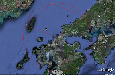
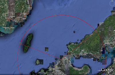
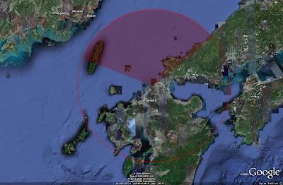
First, a suitable weapon system must be located. For this example a Patriot battery near Fukuoka in Japan will be used, seen in the image below. For this to be accurate, the AN/MPQ-65 position must be identified positively.
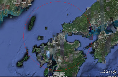
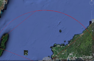
 A ring corresponging to the Patriot's 160 kilometer range must also be placed on the map, as seen below:
 CREATING WEDGES
Step 1
The first step in calculating an approximate engagement zone for the system is to determine the azimuth which the radar is oriented towards. Start by placing a line parallel to the edge of the radar array, as seen below. Using the Ruler tool in Google Earth is best, as it will give you the azimuth of your line.
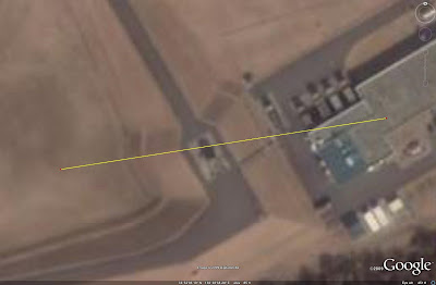 A heading parallel to the face of the radar array would seem to be approximately 81 degrees, travelling from right to left.
Step 2
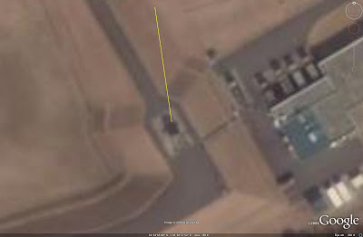
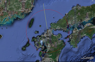
Next, we must determine the azimuth heading of the radar array's center. Knowing that a parallel heading is 81 degrees, we can subtract 90 degrees to get a perpendicular bearing, pointing straight down range from the radar array. This equates to 351 degrees. Mark a line on screen extending away from the radar position on a bearing of 351 degrees. This will appear as shown in the following image:
 Step 3
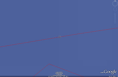
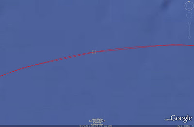
Now, zoom out using the mouse wheel without closing the ruler tool. This allows you to zoom out and then extend the line that has been drawn. Extend the line out past the range ring, as seen below:
 Step 4
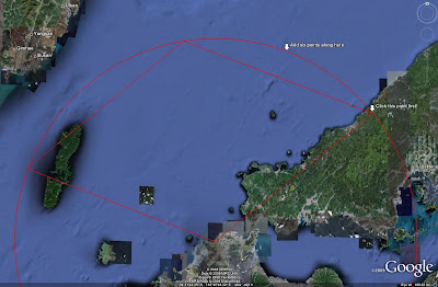
In order to generate the wedge, three placemarks are needed. The first should be placed at the point where the Ruler tool's line crosses the range ring. Zoom in on this point to ensure accuracy, and deposit a placemark as seen in the image below. I have set the placemarks to have zero opacity for their labels, meaning that no text will be displayed.
 Step 5
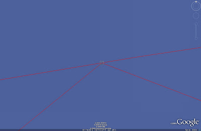
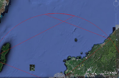
The following process should now be repeated to set placemarks along the boundary of the radar's FOV. 60 degrees left and right or 351 degrees equates to headings of 291 degrees and 51 degrees. Repeat the above processes, dragging lines from the radar out past the range ring on these headings and inserting placemarks where they cross.
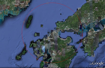
The end result should be as follows, once the ruler tool has been cleared and closed:
 Step 6
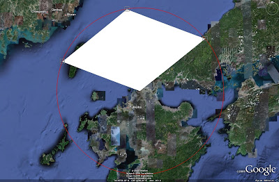
Now, the wedge can be constructed. Using the Area tool, click on screen in four places: the radar, and the three placemarks. Begin with the radar and work counterclockwise. The end result should look like this:
 Step 7
To make the next phase easier, right click on the area placemark in the left-side menu and select Properties. Under the Style, Color tab, enter the following settings:
Lines: Color-red, width-2.0, opacity-100%
Area: select Outlined from the pulldown menu
The end result should resemble this:
 Step 8
Now, zoom in on the three intersect points. After zooming in, it should look like this:
 The goal is to correct the Area's primary points so that they match up with the placemarks on the range ring. Right click on the Area placemark again, select Properties, and drag the points until they are in the correct locations.
A correct example is seen below:
 Step 9
The placemarks for intersect points are no longer required. Deselect them, so that the screen looks like this:
 Step 10
The next step is to shape the two sides of the wedge so that they match the range ring. Each side should be divided by adding a number of new points, which will be placed along the range ring to give the wedge a curved shape. I've found that adding six points between the end points of a given side works well. To better illustrate the idea here, reference the following image:
 The important thing to remember here is to work counterclockwise. You must click on the first point of each side to "activate" that side. Then, when a new point is added, it will align the trailing segment accordingly. If this is done right, after completing a side it should look like this:
 If the proper order is not followed, weird things can happen, and they'll probably look like this:
 Step 11
Repeat the above process for the next side. Remember to click on the center of the three points first, the point that lies along a 351 degree azimuth from the radar. Once complete, turn off the range ring, and this should be displayed:
 Step 12
Now, it is necessary to clean up the wedge segments that were just created. Turn on the range ring and the three placemarks denoting the azimuth limits of the radar, which should look as follows:
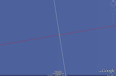
 Placing the points to create segments is not an exact procedure, and if you zoom in on the range ring at any of these points, it may look like the image below:
 Select each point along the curved side of the wedge, including the center and end points, and drag them so that they sit on the range ring. When finished, deactivate the placemarks and range ring. The following wedge should now be present:
 Step 13
All that remains is to fill in the area. Again, right click on the area placemark in the left-side menu and select Properties. Under the Style, Color tab, enter the following settings:
Area: Color-red, select Filled from the menu, and set opacity to 55%
The following image should now be displayed:
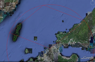
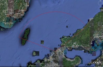
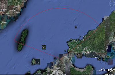
 Zooming out and displaying the range ring, as seen below, we can see that using a wedge instead of a ring is far more accurate.
 EXTRA FEATURES
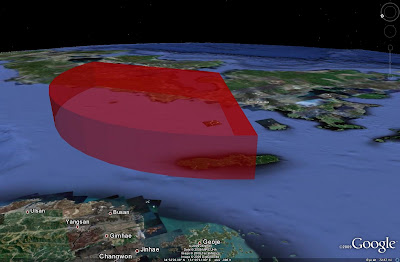
But wait, there's more! Google Earth can be rotated and manipulated to allow 3 dimensional viewing of areas, so why should missile zones be any different? Right click on the area placemark in the left-side menu and select Properties. This time, go to the Altitude tab, enter the following settings:
Under the pull down menu, select Absolute. This must be done first. Under Altitude, enter 30,000 meters, which is roughly equivalent to something close to the Patriot's reach. Click on the box that says Extend sides to ground.
The end result, after you mess about with the viewing angle and altitude, is something like this:
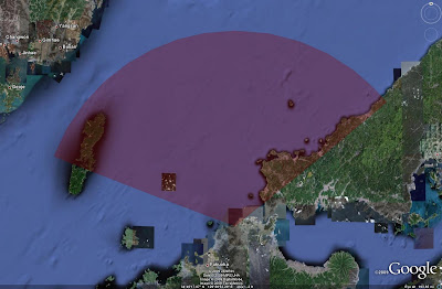
 SAM engagement zones have now become far more amusing. But that's not the end of it. When are SAM systems deployed in any environment without support? Envision a small SAM system with a range of 20 miles and a reach of 15,000 meters in altitude deployed on Orono-shima island, about 40 miles northwest of the Patriot battery. Without matching the wedge to a nonexistant range ring (this is for illustrative purposes, after all), a little tweaking and you can get this:
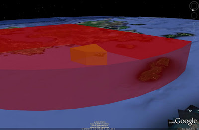 Notice the new engagement zone (yes, you need to use a different color for a different system) inside the Patriot zone.
Now that we know that zones can interact with each other, that can also be exploited. The PAC-3's ERINT ATBM has a 20 kilometer range. Let's suppose that our Patriot battery received the necessary upgrades. Now we have one battery with two different missiles, and two separate engagement zones. By overlaying a 20 kilometer range ring over the existing wedge (this must be done BEFORE you set the wedge for 3D viewing), we can show both zones. Of course, it does help to remember to make the ERINT zone a separate color. If you've done that, it should look like this:
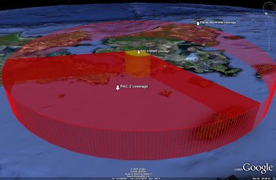
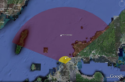 One final point to consider. Remember, the Patriot is typically tied to a specific engagement zone, but the radar can still be moved. This is a far more complicated procedure than simply slewing the S-300P's engagement radar to a new bearing and recoordinating with the battlefield management station, but it can be accomplished nonetheless. The main point here is that the basic range ring does show the capability of the system, but the wedge shows the capability of the system at a given point in time. By combining these two methods and employing a little bit of tweaking here and there, we can get a full, 3D representation of a PAC-3 ERINT battery, as seen below. This highlights the need to have a very in-depth understanding of a given SAM system before attempting any sort of analysis, imagery based or otherwise.
 ONE GLITCH
There is one glitch in Google Earth that should be addressed as a final point to alleviate any cases where readers believe they have done something erroneous. Examine the following image:
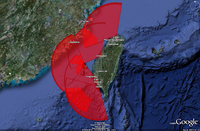 These are the TK-II engagement zones from the Taiwan SAM Network feature displayed in 3D. They are all set to the same altitude of 30,000 meters. Notice how overlap in the wedges can be seen as the boundaries are always visible due to the opacity of the red fill, but along the upper surface there are various patches that do not match with any sort of overlap. Why this occurs, I have no idea. Perhaps this has to do with data inconsistencies in the Earth's surface in that part of the world. At any rate, displaying the wedges in "flat" mode and not 3D gets rid of any such occurrences.
CONCLUSION
You are now authorized to be impressed, and are directed to go forth and employ these techniques to produce your own analysis pieces. Any questions can be directed to the author in the IMINT & Analysis Forum, by blog comment, or by e-mail. Go forth and analyze.
SOURCES
-Satellite imagery provided courtesy of Google Earth
SAM Ranges taken from Jane's Land-based Air Defence, various editions
The AN/MPQ-65
The normal method used to illustrate SAM engagement ranges graphically is to display a ring around the site corresponding to the engagement range of the system. As the theory goes, any aircraft inside of that ring could potentially be engaged by the system. With certain types of strategic SAM systems, however, this method is not entirely accurate. Engagement radars are often sited and aligned along a certain bearing. If the radar is not capable of continuous 360 degree rotation, the radar's field of view in azimuth dictates the engagement zone of that deployed SAM battery at a given time.
Consider the following examples. Taiwan's Tien Kung SAM systems are deployed from fixed, silo-launched positions, supported by fixed, hardened Chang Bei LPARs. Given that these radars are occupying fixed positions, the engagement zone of the SAM system is dictated by the 120 degree FOV of the radar, 60 degrees to the left and right of center.
The Russian S-300P series of SAM systems and the American Patriot missile system operate in a similar manner. These two mobile SAM systems operate by deploying their engagement radars in a given position. The Patriot's AN/MPQ-65 radar has the same 120 degree FOV as the aforementioned Chang Bei, providing it with a similar engagement zone. The difference between the AN/MPQ-65 and the engagement radars employed by the S-300P series is that the Patriot's radar also performs acquisition functions. The S-300P's radars are cued by 36D6 or 64N6 series radars. Mounted on towers or on mobile vehicles or trailers the S-300P's radars can easily be rotated to face an inbound threat. Ergo, the S-300P series SAM systems are not as "tied in" to a particular zone as the Patriot is. While the S-300P's engagement radars offer azimuth sector coverage of between 90 and 105 degrees depending on the variant, and operationally they will typically be tied to a certain sector for deconfliction purposes, the system is credited with full 360 degree capability due to mounting the engagement radars on rotating platforms. The AN/MPQ-65, on the other hand, is emplaced statically to facilitate target acquisition, and is therefore not a "true" 360 degree coverage system, despite its mobility.
How, then, to better illustrate these concepts graphically? The answer is to use a wedge shape denoting the field of view of the engagement radar array in systems for which a circular range ring would not be appropriate. Google Earth serves as a good platform for developing and displaying these shapes. The process for doing so will be described below. Readers are advised to read the instructions completely before trying this for themselves.
FUKUOKA PATRIOT
First, a suitable weapon system must be located. For this example a Patriot battery near Fukuoka in Japan will be used, seen in the image below. For this to be accurate, the AN/MPQ-65 position must be identified positively.
 A ring corresponging to the Patriot's 160 kilometer range must also be placed on the map, as seen below:
 CREATING WEDGES
Step 1
The first step in calculating an approximate engagement zone for the system is to determine the azimuth which the radar is oriented towards. Start by placing a line parallel to the edge of the radar array, as seen below. Using the Ruler tool in Google Earth is best, as it will give you the azimuth of your line.
 A heading parallel to the face of the radar array would seem to be approximately 81 degrees, travelling from right to left.
Step 2
Next, we must determine the azimuth heading of the radar array's center. Knowing that a parallel heading is 81 degrees, we can subtract 90 degrees to get a perpendicular bearing, pointing straight down range from the radar array. This equates to 351 degrees. Mark a line on screen extending away from the radar position on a bearing of 351 degrees. This will appear as shown in the following image:
 Step 3
Now, zoom out using the mouse wheel without closing the ruler tool. This allows you to zoom out and then extend the line that has been drawn. Extend the line out past the range ring, as seen below:
 Step 4
In order to generate the wedge, three placemarks are needed. The first should be placed at the point where the Ruler tool's line crosses the range ring. Zoom in on this point to ensure accuracy, and deposit a placemark as seen in the image below. I have set the placemarks to have zero opacity for their labels, meaning that no text will be displayed.
 Step 5
The following process should now be repeated to set placemarks along the boundary of the radar's FOV. 60 degrees left and right or 351 degrees equates to headings of 291 degrees and 51 degrees. Repeat the above processes, dragging lines from the radar out past the range ring on these headings and inserting placemarks where they cross.
The end result should be as follows, once the ruler tool has been cleared and closed:
 Step 6
Now, the wedge can be constructed. Using the Area tool, click on screen in four places: the radar, and the three placemarks. Begin with the radar and work counterclockwise. The end result should look like this:
 Step 7
To make the next phase easier, right click on the area placemark in the left-side menu and select Properties. Under the Style, Color tab, enter the following settings:
Lines: Color-red, width-2.0, opacity-100%
Area: select Outlined from the pulldown menu
The end result should resemble this:
 Step 8
Now, zoom in on the three intersect points. After zooming in, it should look like this:
 The goal is to correct the Area's primary points so that they match up with the placemarks on the range ring. Right click on the Area placemark again, select Properties, and drag the points until they are in the correct locations.
 A correct example is seen below:
 Step 9
The placemarks for intersect points are no longer required. Deselect them, so that the screen looks like this:
 Step 10
The next step is to shape the two sides of the wedge so that they match the range ring. Each side should be divided by adding a number of new points, which will be placed along the range ring to give the wedge a curved shape. I've found that adding six points between the end points of a given side works well. To better illustrate the idea here, reference the following image:
 The important thing to remember here is to work counterclockwise. You must click on the first point of each side to "activate" that side. Then, when a new point is added, it will align the trailing segment accordingly. If this is done right, after completing a side it should look like this:
 If the proper order is not followed, weird things can happen, and they'll probably look like this:
 Step 11
Repeat the above process for the next side. Remember to click on the center of the three points first, the point that lies along a 351 degree azimuth from the radar. Once complete, turn off the range ring, and this should be displayed:
 Step 12
Now, it is necessary to clean up the wedge segments that were just created. Turn on the range ring and the three placemarks denoting the azimuth limits of the radar, which should look as follows:
 Placing the points to create segments is not an exact procedure, and if you zoom in on the range ring at any of these points, it may look like the image below:
 Select each point along the curved side of the wedge, including the center and end points, and drag them so that they sit on the range ring. When finished, deactivate the placemarks and range ring. The following wedge should now be present:
 Step 13
All that remains is to fill in the area. Again, right click on the area placemark in the left-side menu and select Properties. Under the Style, Color tab, enter the following settings:
Area: Color-red, select Filled from the menu, and set opacity to 55%
The following image should now be displayed:
 Zooming out and displaying the range ring, as seen below, we can see that using a wedge instead of a ring is far more accurate.
  EXTRA FEATURES
But wait, there's more! Google Earth can be rotated and manipulated to allow 3 dimensional viewing of areas, so why should missile zones be any different? Right click on the area placemark in the left-side menu and select Properties. This time, go to the Altitude tab, enter the following settings:
Under the pull down menu, select Absolute. This must be done first. Under Altitude, enter 30,000 meters, which is roughly equivalent to something close to the Patriot's reach. Click on the box that says Extend sides to ground.
The end result, after you mess about with the viewing angle and altitude, is something like this:
 SAM engagement zones have now become far more amusing. But that's not the end of it. When are SAM systems deployed in any environment without support? Envision a small SAM system with a range of 20 miles and a reach of 15,000 meters in altitude deployed on Orono-shima island, about 40 miles northwest of the Patriot battery. Without matching the wedge to a nonexistant range ring (this is for illustrative purposes, after all), a little tweaking and you can get this:
 Notice the new engagement zone (yes, you need to use a different color for a different system) inside the Patriot zone.
Now that we know that zones can interact with each other, that can also be exploited. The PAC-3's ERINT ATBM has a 20 kilometer range. Let's suppose that our Patriot battery received the necessary upgrades. Now we have one battery with two different missiles, and two separate engagement zones. By overlaying a 20 kilometer range ring over the existing wedge (this must be done BEFORE you set the wedge for 3D viewing), we can show both zones. Of course, it does help to remember to make the ERINT zone a separate color. If you've done that, it should look like this:
 One final point to consider. Remember, the Patriot is typically tied to a specific engagement zone, but the radar can still be moved. This is a far more complicated procedure than simply slewing the S-300P's engagement radar to a new bearing and recoordinating with the battlefield management station, but it can be accomplished nonetheless. The main point here is that the basic range ring does show the capability of the system, but the wedge shows the capability of the system at a given point in time. By combining these two methods and employing a little bit of tweaking here and there, we can get a full, 3D representation of a PAC-3 ERINT battery, as seen below. This highlights the need to have a very in-depth understanding of a given SAM system before attempting any sort of analysis, imagery based or otherwise.
 ONE GLITCH
There is one glitch in Google Earth that should be addressed as a final point to alleviate any cases where readers believe they have done something erroneous. Examine the following image:
 These are the TK-II engagement zones from the Taiwan SAM Network feature displayed in 3D. They are all set to the same altitude of 30,000 meters. Notice how overlap in the wedges can be seen as the boundaries are always visible due to the opacity of the red fill, but along the upper surface there are various patches that do not match with any sort of overlap. Why this occurs, I have no idea. Perhaps this has to do with data inconsistencies in the Earth's surface in that part of the world. At any rate, displaying the wedges in "flat" mode and not 3D gets rid of any such occurrences.
CONCLUSION
You are now authorized to be impressed, and are directed to go forth and employ these techniques to produce your own analysis pieces. Any questions can be directed to the author in the IMINT & Analysis Forum, by blog comment, or by e-mail. Go forth and analyze.
SOURCES
-Satellite imagery provided courtesy of Google Earth
SAM Ranges taken from Jane's Land-based Air Defence, various editions
The AN/MPQ-65


8 comments:
Amazing!
So when are you going to have the Russian SAM network in 3D for download? ;-)
May I suggest you take a look at nasa's worldwind (http://worldwind.arc.nasa.gov/) for visualization? It's very similar to google earth, but much more friendly to visualizing stuff like this. We're currently integrating a feature like this into a GCCS app btw. The visualization is somewhat similar. However, the ELINT is vastly more complicated than a simple circle. It's generally described as sample points in 3d space from the central point, interpolated to make a nice radar "bubble" kinda thing.
I think your measurements are going to be a bit off due to not correcting for the geodesic curvature of the earth.
Any measurement is going to be a bit off unless you take that into account, but it's close enough. Same as how you have to take the Earth's rotation into account when estimating ballistic missile ranges.
Google Earth is also not 100% accurate anyway, but that's another story. For this purpose, it's good enough.
Sean,
Your model is great but complex to build.
There's probably a few people in the GE world who are capable of writing a "little" program to do this with minimum user input.
I think you would need the following variables:
- X,Y location of site
- Azimuth of center line from X,Y
- Width of beam or missile fly-out limitations (plus/minus degrees)
- Range (max/min) (missile and/or radar)
- Max Altitude (missile and/or radar)
- Selectable color of solid
- Degree of transparency of solid
I need to think about displaying terrain masking effects - the Taiwanese examples with the majority of the envelope over water tends to obviate this issue. Immediately coming to mind is ray tracing, which leads to computational issues.
Another alternative would be to generate a group of specific system "standard" models and then plop them down where they need to be. Or even sexier, would to be able to tie the associated EW and tracking radars based on their locations with the specific firing battery locations.
Advise of additional data to consider/display in v. 2.0 welcomed.
I'll think about posting a challenge on the appropriate GE forum.
Rip
It is complex, but after doing a few of them I found that I could generate them relatively quickly once I got it all figured out.
Getting an application to do it for you is a great idea, but I have absolutely zero skill in that regard. If you can figure something out or have a line on somebody who might be able to give it a shot, let me know. That'd be greatly appreciated.
I searched how to create an accurate circle in GE. What I found is: http://dev.bt23.org/keyhole/circlegen/ Nothing better. Tried using app named "circle generator", but I was astonished when it created more egg-like "circle". Whas it problem of mine or application, don't know, but I suggest using link written above.
By the way, superb analysis lesson ;)
Post a Comment