Showing posts with label Google Earth. Show all posts

Friday, June 1, 2012

29 May Imagery Update

First, some housekeeping.  Given that this is the first serious attempt at documenting anything interesting in the most recent Google Earth imagery update, here's how it will work.  The post title will have the date of the imagery update as displayed in the Google Earth imagery update kml file.  So don't be confused when today is 1 June and you see the post title with 29 May!  Also, I've tagged the post with the Google Earth label, and created a new one called Imagery Update.  From this point forward if you find the Imagery Update tag in the label list, you can then view all of the relevant articles talking about Google Earth's imagery updates.

Also, I'm not going to detail every little thing or every updated location.  If you want that, head over to the Google Earth Blog.  They do a great job of both announcing updates and listing locations as they're discovered.  This will serve to highlight some of the amusing new imagery, or maybe amusing updated imagery, of places of interest to myself and readers of this site.

On to the update.  The Google Earth imagery update on the 29th was pretty impressive.  Lots of new imagery incorporated, mostly a bunch of smaller cels. 

One new location now visible in high resolution is the Nenoksa SLBM test complex west of Severodvinsk.  Which sounds like a really great place for an I&A Facility Overview!

There's new imagery of a lot of the PLA's 830th Brigade complexes at Kunming, but nothing earth-shattering to report.

May 2011 historical imagery of the southwestern 53T6 ABM site around Moscow shows some sort of work at one of the silos, and there's a GAZELLE transloader parked in the vehicle area.

In terms of the SAM Site Overview file, an interesting development is the deployment of a 55Zh6 TALL RACK CVLO VHF-band radar north of Orsha in Belarus.  This makes two of the systems identified in Belarus at this time.

The most irritating update is a block of new imagery from late 2011 in Baku, Azerbaijan...which is still of no help as to locating their S-300PMU-2 components.

Those are the most interesting or significant things I've noticed so far exploring the new imagery.  If I locate anything else, I'll update this post and kick it back to the top of the page.

Thursday, May 17, 2012

Google Boats?

According to a news piece posted by AOL, Google is developing the ability to track and display the locations of ships at sea.

All of them.

Well, at least those actively using AIS transponders, but still.

This is a pretty interesting development, if you ask me.  Some of the benefits are obvious, and are mentioned in the article.

Then there's the fact that you could theoretically track the movement of military forces worldwide.  Provided they operate with AIS transponders active, that is.

I'd think that this represents a great tool to exploit off of the Horn of Africa.  Military vessels in the area with transponders active could act like homing beacons for shipping in the area, guiding them through protected waters and serving as a pirate deterrent.  The authors naturally assume that such new technology would obviously represent some sort of terrorist tool for attacking targets (because what else is Google Earth but a mapping program of terrorist targets, right?), but if American, Chinese, or whoever's naval units are operating in the clear, hey, go ahead and try it.  I'm willing to bet that in the battle of terrorist vs. 5 inch round or terrorist vs. CIWS, the winner will not be the guy with nefarious intentions.  Plus, in case they haven't noticed, terrorists and pirates are already attacking boats.

The really interesting bit of the article is Google's plan to map the entire seafloor in high resolution over five years.  Again, the assumption is that this will lead to all sorts of security problems when crashed spy satellites are located and the Chinese or Russians go out to lift them off the bottom.  Always with the negative waves, Moriarity.  Always with the negative waves.  Me, I'd like to see them locate Jack Weeks' A-12, to finally put an end to one of the unsolved tragedies of the CIA's OXCART program.

Of course, locating K-129 would be amusing too...we'd then know just how much of the sub was lifted off of the bottom by the CIA.  I'm not sure which would be more amusing, finding only a few pieces of the sub on the bottom, or the entire thing.

The article closes with the following line from an unnamed intelligence community source, after a brief bit about how Google services have little intelligence utility whatsoever in their minds:  "Just because you have the data, doesn't mean you can analyze the data or know how to use it."

Sure, I'll take that as a challenge.  Or maybe a mission statement...

And see?  I told you I'd be posting here again.

Friday, August 20, 2010

Google Earth & Law Enforcement

INTRODUCTION

GIS programs like Google Earth offer a lot of capabilities that can be exploited by various professional agencies. Access to overhead imagery, three dimensional environments, and the ability to edit and distribute information through the program make Google Earth in particular a useful analytical tool. One potential use for the program which seems to be underutilized is in the realm of law enforcement. While Google Earth is not a real-time imagery browser, a number of the capabilities it offers can enhance the performance of law enforcement functions.

This article represents a sanitized and reduced-scope version of a professional training tool developed by the author for a client in the Southwestern United States. It is intended to provide a basic overview of some of the capabilities of Google Earth valuable to law enforcement agencies and brief descriptions of how they can be effectively exploited.

AREA EXPLOITATION

One of the most obvious aspects of Google Earth that can be exploited is the ability to analyze the local environment. This can be of critical importance to any law enforcement agency planning surveillance or an offensive operation in a potentially unfamiliar area. While traditional maps and charts can offer a degree of understanding, Google Earth offers a far more robust set of features for extracting data.

Layout

The overhead nature of Google Earth provides an excellent medium for analyzing the layout of a given area, be it an urban, rural, or uninhabited location. Simply navigating to a point of interest provides the user with a significant amount of information. The status bar along the botom of the screen provides, from left to right, the date the imagery was acquired, the coordinates, the elevation, and the eye altitude.

The imagery capture date is significant as it allows the user to put the image in context. An older image may not show current features such as roads or buildings. Alternatively historical imagery can be browsed to view changes to the area that have been made over time.

The coordinates and elevation data are directly tied to the position of the on-screen cursor. As the cursor is moved around the screen, the coordinates and elevation data will change to account for the current position.

The eye altitude is the apparent position of the viewer above the image. For example, an eye altitude of 5,000 feet indicates that the image is what would be seen by an observer 5,000 feet above ground level.

Once an area of interest has been located, various features can be viewed by selecting different options in the Layers menu found at the bottom left of the screen. Some relevant features include roads, which will bring up the paths and names of various roads in an area, and other locations such as restaurants, bars, hospitals, water features, and terrain.

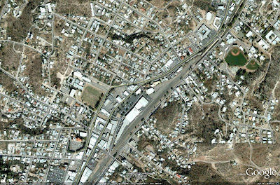
The following image depicts Nogales, Arizona, with the roads feature activated. Notice how both the pathways and names of the roads are overlaid on the overhead imagery.
Examining Terrain

Google Earth provides many ways to view the environment in three dimensions. The most common involves viewing the terrain in a given area. By selecting the terrain feature in the Layers menu, three dimensional terrain is loaded into the image.

Terrain data can also be manipulated to exaggerate features, making them more apparent to the observer. In the Options menu, accessed through the Tools section of the taskbar at the top of the screen, a number from 0.5 to 3 can be entered for Elevation Exaggeration. The default value is 1, which displays terrain at the natural scale.

Once terrain features are activated, pressing and holding the mouse wheel will bring up a special cursor on the screen. Pulling back on the mouse will tilt the image allowing terrain to be viewed in 3D. Pushing forward will then return the image to its traditional overhead state.

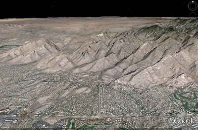
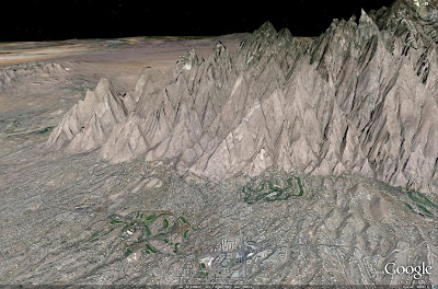
Consider the following two images, both depicting the terrain north of Tuscon, Arizona. Both images show the same approximate areas. The first image depicts the terrain with an elevation exaggeration value of 1, while the second image depicts the terrain with an elevation exaggeration value of 3. Notice how the features in the second image are greatly exaggerated to bring out their details.

Cities in 3D

3D buildings are available for many major metropolitan areas in Google Earth. These buildings are available in two formats, basic greyscale shapes and photorealistic structures. Greyscale shapes approximate the basic shapes of the buildings they represent, while the photorealistic versions have digital photographs applied to their surfaces to provide a more realsitic approximation of the structures.

3D buildings are accessed in the Layers menu, with the option for loading either grayscale, photorealistic, or both types of buildings available. These structures are created by Google and its user community using a program called Google Sketchup. Buildings are submitted to Google for inclusion into the database, which ensures that the most accurate structures are incorporated and are properly aligned with the imagery. Users can also create their own structures and access them locally.

Phoenix, Arizona provides a suitable environment for examining both types of 3D structures available. In this case, as is the case with many locations, downtown Phoenix is primarily populated with photorealistic buildings, with the outlying areas relying primarily on greyscale structures.

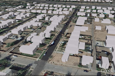
The image below illustrates a residential area northwest of downlown Phoenix. This area has been constructed using greyscale buildings.
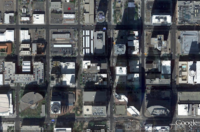
The image below illustrates downtown Phoenix. The area has been rendered using photorealistic structures for added detail. Note how segments of the overhead imagery for Phoenix has been incorporated into the buildings for additional effect, including the imagery of a tennis court atop the lower level of the Ernst & Young complex.
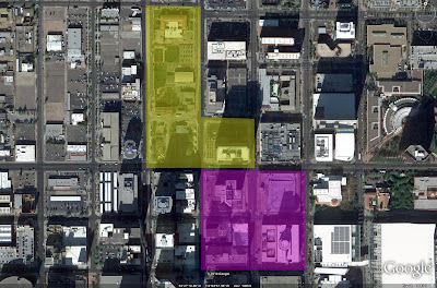
The following image depicts a location in Phoenix where both types of building can be seen.
Uses

The various layout features of Google Earth lend themselves to a wide variety of law enforcemnt applications. Traditional activities such as foot or vehicle patrol routes can be planned to maximize the coverage available, ensuring that high interest areas are given the required amount of attention. Routes to and from locations of interest can be evaluated. By using the roads feature, any route can be properly planned, including those through areas or to locations which are not well known.

Apart from the basic features, having a three dimensional environment to exploit is a very useful tool. The most obvious advantage conferred by a three dimensional environment is the ability to evaluate fields of view from various positions. When planning an approach to a given location, for example, a three dimensional environment allows law enforcement officials to evaluate the most unobtrusive approach to a given location, taking the greatest advantage of surrounding structures or terrain. Likewise, in a situation where sniper support or some other form of overwatch is required, a three dimensional environment can be used to evaluate the most advantageous deployment locations for these assets, maximizing their fields of view of the area of interest with regard to other obstructions in the area.

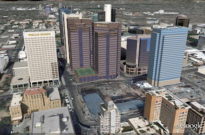
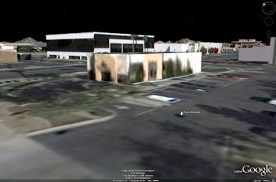
Consider the following example. In this instance, assume that the point of interest is a location to which police must be dispatched to deal with a developing situation. In an encounter such as this, success is often related to the ability to arrive with enough stealth to apprehend most or all of the individuals involved. Having a three dimensional view of the environment can be a significant asset in planning the proper route of approach.

In the first image, it can clearly be seen that a direct approach from the north is undesirable. The parking lot of the building across the street provides a clear field of view from the POI to identify any approaching units.
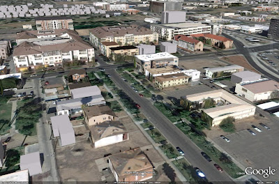
Likewise, an approach from the west may not be desirable. The following image illustrates that even with the building across the street to the west from the POI, the main street leading to the intersection can be monitored to a degree.
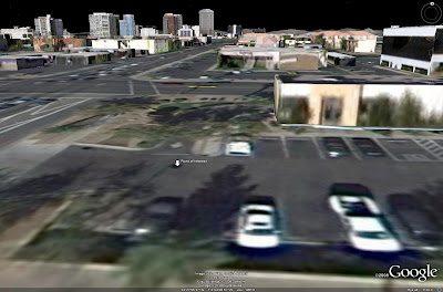
Approaching from the east and taking a less direct route can afford the greatest element of suprise. The building directly adjacent to the POI, combined with the large structures across the street to the northeast, can be used to mask the majority of any approach, as seen in the image below.
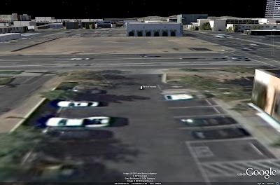
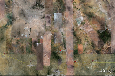
In this case, the route of approach can be seen in an overhead view in the image below.
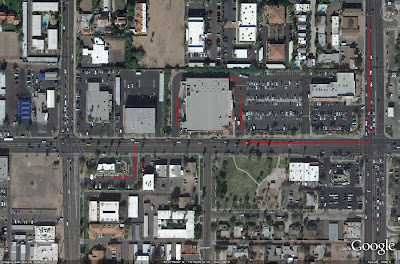
Other routes can certainly prove as or more effective, particularly from the south, but this example illustrates how a three dimensional environment can be significantly useful in developing effective strategies.

The eye altitude information can be exploited to enhance helicopter support for organizations possessing these assets. Recall that the eye altitude represents the position of the observer above the image. This data can be used to set altitudes for helicopter assets to ensure that they are able to effectively monitor a given area. Attention should be given to the calibration of the altimeters in the helicopters. Most altimeters are calibrated to sea level. In this case, the correct altitude would be a combination of the eye altitude and the elevation. If the desired eye altitude is 5,000 feet and the local elevation is 1,000 feet, then the distance above sea level of the patrol should be reported as an altitude of 6,000 feet.

DATA INCORPORATION

Having a tool such as Google Earth to evaluate the layout of a given location can certainly enhance law enforcement activities, but where Google Earth becomes truly valuable is when user-generated data is incorporated into the program. This allows for a host of data analysis techniques to be applied. Data is entered into Google Earth using various annotations which can appear on-screen. These include placemarks, paths, polygon shapes, and external images.

Placemarks

The most effective way to incorporate data into Google Earth is by developing a set of placemarks. Placemarks appear on-screen and can be configured to display relevant details when clicked, providing a useful distribution medium for this information. It is important to develop an effective method of cataloging and detailing placemark files to ensure that they provide clear, concise information.

The following image depicts a portion of Phoenix displaying various placemarks denoting law enforcement activity. In this example, three different placemarks have been used. The blue vehicle denotes action by a patrol car, the orange silhouette denotes action by an office on foot, and the red triangle denotes hostile activity.
When clicked, each placemark will bring up a window such as the one seen in the image below.
In this case, the placemark has been filled with data according to the following template:

Activity
Arresting Officer (AO)
Date
Time
Location
Details
Report

This allows any user to access the relevant data about the incident in question noted by the palcemark. There is also a location to incorporate a weblink to any relevant paperwork or reporting on the incident, allowing it to be quickly accessed.

The formatting and content of the information on display can be managed locally but should always employ the same basic template for ease of use. In this example, clicking on any of the placemarks in the image above would result in the same window being displayed, the only difference being in the information contained therein.

To add information to a placemark, one simply edits the Edit Placemark box which is displayed when a placemark is first added to Google Earth. To edit the placemark after it is entered, simply right click on it and select Properties to bring up the same Edit Placemark box.

The previous examples were generated by simply copying and pasting the basic template into the dialog box and filling in the relevant details. To unclutter the screen, the placemark labels have their opacity set to zero in the Edit Placemark dialog box. This hides any text and only displays the icons. It does not affect the displaying of the relevant data when the placemarks are clicked in Google Earth. Leaving the label opacity set to the default of 100% will result in the placemark name being displayed adjacent to the placemark. When a large number of placemarks are displayed on-screen, this can make for a very cluttered environment.

It should be noted that the dialog box is HTML compatible, allowing the text to be highlighted or otherwise edited. However, due to this fact it is necessary to incorporate "br" following each line of text to denote a break or to simulate hitting the return key. The quotation marks should be replaced with < or > on either side of the "br", but this cannot be effectively shown here due to formatting restrictions.

If desired, there are resources available which can be used to develop a unique set of placemarks if those found in Google Earth do not represent the best method of display.

Placemarks can be organized using the My Places section of the Places menu at the left of the screen. By right clicking on My Places, Add Folder can be selected, allowing the user to add a named folder to store placemarks. Likewise, subfolders can be added for further organization. In this case, the placemarks have been stored in a folder titled Precinct 117, in a subfolder for Arrests. This subfolder is then divided into July and August 2010 subfolders. By selecting or deselecting various fodlers and subfolders, the user can manipulate the data he or she wishes to display and evaluate.

Placemarks can be further enhanced by incorporating images. In this case, an image is added by incorporating a web or network link to the relevant image. This feature can be used to provide images of activity, evidence, or other information of relevance. Images can be added to any placemark using the following HTML text: img src="XXX" /img The XXX inside of the quote marks is replaced with the network or web link to the image. Both img src="XXX" and /img are contained within the < and > brackets, which again cannot be fully shown here. In the following image, the dialog box displayed has a picture added.
Images should be stored locally on a shared fileserver if possible. This allows users to use the same basic file path to locate images, removing some of the difficulty involved.

Paths and Polygons

Paths and polygons can also be effective tools. They are added using the path or polygon tools at the top of the screen. In a polygon, clicking on the screen will place a corner, and in a path, clicking on the screen will drop a point along the route. Polygons can be filled or outlined, and both features can have their colors, width, and other features edited. Also, both features have dialog boxes which can be edited using the same method as that found in the placemarks. Clicking on any point along the path or polygon will result in the dialog box being displayed.

The image below denotes a use for the path feature. In this example two paths are denoted. The green path denotes a patrol route for a patrol car, with the blue path denoting a patrol route for an officer on foot.
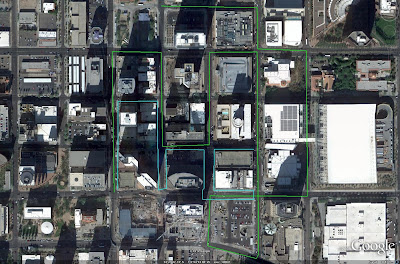
The image below denotes a use for the polygon feature. In this example different colored polygons are being used to denote different gang turfs.
A placemark database can be saved by selecting the most upper-level folder, which in this case would be Precinct 117, right clicking, and selecting Save As. This will save placemarks as well as any other features such as paths or polygons that are present. Alternatively, Google Earth saves the same files in the My Places directory upon exit. When exiting Google Earth, the Server Log Out option under the File menu in the menu bar should be selected first. This ensures that the placemark data is saved without loss of data. At times Google Earth can fail to save recently entered data if the program is simply exited.

Network Links

One way of effectively sharing placemark data, and ensuring that it is entered consistently using a prescribed format, is to manage the files on one computer. The placemark files would then be shared to other users using a network link. In this case, it is necessary to manage the placemark files as a separate dataset, loading the files into Google Earth when editing or data entry is required.

In this method, the user would load a placemark dataset into Google Earth by clicking Control-O and selecting the dataset from a shared network drive or internet source. Any editing is then done, before the dataset is re-saved to the previous location. To access the information, a network link is generated. This is done by selecting Add Network Link from the Add menu in the menu bar at the top of the screen. In the dialog box that appears, the pathway to the file is included in the Link box. This network link can then be saved independently and shared to various users via email or by posting it to an intranet or shared server. When the users open the network link, they will immediately have access to the dataset.

ANALYTICAL USES

While it can take a considerable amount of time to initially generate a dataset, once it has been generated and proper procedures have been developed for incorporating new data it can prove to be a very useful analytical tool.

Many of the previously mentioned law enforcement functions can be significantly enhanced by employing a robust dataset in Google Earth. For example, simply marking and tracking the locations of arrests or crimes can be used to adjust patrol routes to ensure that they pass through areas with a significant amount of activity. In this instance, proper use of Google Earth and a developed dataset can eventually serve as a deterrent to criminal activity.

Likewise, a developed dataset can allow a law enforcement organization to properly allocate resources in a region, ensuring that high-crime areas have the necessary resources to adequately serve the public. This is a prime example of the financial benefit of geospatial information technology.

Counterdrug Operations

One aspect of law enforcement where GIS technologies such as Google Earth can be effective is in counterdrug operations. Using the aforementioned techniques, locations of drug-related arrests or locations of drug-related points of entry or facilities can be tracked.

Consider the following image. Assuming that the marked locations are distribution points of drugs entering the United States from Mexico, a host of analytical options can be described.
Once locations are known and marked, various options are available for analysis. The most obvious involves discerning potential routes of travel for distribution. Simple analysis can be performed, asking questions such as "do they travel at night" or "are they using heavy or light vehicles". Knowing when and how drugs are being transported can serve to more accurately identify potential routes of travel. Light vehicles may be more likely to make use of minor or even unpaved roadways in a given region, which are often patrolled far less frequently. Being able to exploit a gods-eye view of the area can often help to make such analytical decisions easier to understand.

Furthermore, being able to visually observe drug-related activity in a program such as Google Earth can aid in the identification of distribution facilities or production centers. When a number of drug-related arrests, particularly those involving the sale of controlled substances, are marked in a given area, analysis can be performed on the dataset to identify likely distribution centers. One such method can be to determine the facilities relatively equidistant from each arrest, and marking them for further investigation. Other intelligence sources can also be used in combination with the available data to effectively analyze the overall picture in a given area or region.

Gang Activity

Gang activity can also be evaluated using Google Earth. A previous image depicted two notional gang territories in Phoenix. Simply marking such regions can be a useful endeavor. Areas where two or more territories abut against one another can be potentially volatile regions. A logical use for this data would be to manage patrols in the area to forestall any violent action to a degree.

Territories themselves can be evaluated and marked using analysis of gang symbology in a region. A previous example depicted an image of gang symbology inserted into the dialog box associated with a placemark. Marking these occurrences in Google Earth can serve as a way of identifying the breadth of a particular gang's territory. Furthermore, an officer or agent assigned to a particular area can exploit such a placemark as a reference source on the potential symbology associated with a region. Then, if a different set of symbology is discovered, gang territories can be updated accordingly. This can aid in the understanding of the fluidity of territories in some areas.

Border Security

One of the most critical problems facing law enforcement agencies in some areas is border security. A three dimensional viewer such as Google Earth can be an effective tool in evaluating and combating border incursions.

Having three dimensional terrain to evlauate can often provide insight into potential routes of ingress by illegal aliens. Being able to visualize the terrain in a region can aid law enforcement agencies in discerning how illegals manage to cross the border unobserved. Often, terrain can be exploited by these criminal groups to mask their presence from population centers in a given region. The analyst need simply ask the question "where can they be hidden from view" to discover potential ingress routes which may not have been apparent simply by examining a two dimensional map of the area.

Such analysis can also aid in other areas, such as discovering border crossing zones where illegal substances are brought into the nation. While these techniques alone will not necessarily identify these areas conclusively, they can certainly aid in developing a starting point for any investigation.

CONCLUSION

Google Earth by itself is not going to put an end to crime in America. Nor should it be used as the sole source or method for performing analysis and evaluating potential courses of action by any law enforcement agency. However, it can clearly be seen that effective analysis coupled with a robust set of data to evaluate can most definitely have benefits to any law enforcement agency. Law enforcement agencies would certainly benefit from proper exploitation of this freely available resource.

SOURCES

-Satellite imagery provided courtesy of Google Earth

Saturday, March 20, 2010

Menu Fail

Google has changed Google Earth's Layers menu. They've basically consolidated a lot of things into one "button", Places of Interest. Activating this will open what used to be city and town names, shops, restaurants, parks, schools, banks, train stations, airports, etc. In an effort to consolidate and make things more streamlined, they've basically made it far less useful and a lot more confusing.

First off, you'll notice that there are a good deal fewer placemarks now. For example, a lot of schools seem to have disappeared. These placemarks are all altitude restricted as well, meaning that certain things disappear once you zoom out far enough. This makes it a lot more complicated to do things like find schools or restaurants near your home, unless you're only concerned with what is practically right across the street. The only positive to this change is that certain places, like airports or restaurants, have kept their unique placemarks.

Secondly, the place names don't appear unless you click on the icon to display the ddescriptive balloon. This doesn't really matter for shops and the like, but is very irritating when it comes to displaying the names of population centers using this new feature. If you want to see the old-style city names and markers, you now have to activate the Labels "button" in the Borders and Labels folder. OK, doing this will activate ALL of the labels, including those for islands, water bodies, and the like, which isn't all that bad for the most part. The problem is that it also activates all of the alternate or foreign place names as well, giving you two names for a lot of locations. This can make images very cluttered. It also isn't consistant. Mountains, for example, are included in Places of Interest, while islands are in Labels. Shouldn't all the geographic features be in the same place?

Personally, I find the second problem far more irritating than the first. I wouldn't mind if they went with either the Western or native names for the cities and whatnot, but having to have both of them displayed if you want or need them on-screen makes life a little more difficult. The only solution at this point is to develop my own series of placemarks for these locations when I need them, adding more time and effort to any project. If the point of doing this is to make things more streamlined and simpler to use, Google has, in my opinion, failed. Something that is intended to be simpler should not require the expenditure of more time and effort to get it to do what you need.

There's also the issue that a lot of their placemarks draw data directly from Wikipedia, but we won't touch that one today.

Yeah, I know I'm what would probably be considered a "niche" user of Google Earth, exploiting it for very specific and specialized purposes, but the first point I discussed above makes life more complicated for everyone. Hopefully, this will turn out to be part of a rolling update to remake the entire Layers menu. But if not, Google just made life more difficult for a lot of users, and if you ask me, it was a completely unnecessary change. Unless, of course, they just had to clear out the disk space to throw up more new imagery, but the probability of that being the reason is ridiculously remote given the fact that Google could buy new servers with the same frequency that I buy obnoxious death metal CDs.

What are your thoughts? Post them in the comments!

Wednesday, March 17, 2010

SAM Site Overview Alteration

I've been exploiting Terra Server, Bing Maps, and a few other amusing online imagery sources to examine some areas of Google Earth that are either 1) not covered in high resolution, or 2) have not been updated with newer imagery for quite some time. I've discovered a number of things that will be included in the SAM Site Overview, beginning with the next update. This might be a little confusing at first glance. For example, I've found imagery from 2009 showing that the 64N6E site in China near Dalian is now active. I will be changing the placemarks in the file to reflect this, as Google Earth's imagery of that region is still a bit dated. So, you'll see an empty 64N6E location, but have a placemark telling you that it is active. No, I haven't lost my mind, I'm just beginning to incorporate other sources into the database on a larger scale. Anything potentially weird like that example will always be explained in the Notes section of the placemark. Just thought I'd give everyone a heads-up before I start doing something potentially confusing.

Monday, November 23, 2009

Taiwan Isn't Pleased

A Taiwanese news article posted online on November 21st had an interesting topic: an IMINT & Analysis forum member's article posted to militaryphotos.net detailing Taiwan's air defense facilities. In a roundabout way, this site was also mentioned, as the article stated that the air defense overview's author "was working with another that had previously worked on Taiwan air defense, and photos/imagery". Hey, that's me, referring to my May 2009 piece on Taiwan's Strategic SAM Network.

The news piece claims, by way of comments from ROCAF officials, that the sites detailed are public knowledge and not secret, and that the distribution of commercial satellite imagery makes it more difficult to keep such facilities concealed. That's all well and good, but they have to be privately annoyed, given the fact that a good deal of these sites are in fact censored in the most recent Google Earth imagery. If they weren't meant to remain hidden from public view, why bother censoring the sites?

Of course, that didn't stop me in the least from utilizing Google Earth's features to extract uncensored images of the sites and display the relevant imagery. Besides, if anyone thinks that the Chinese military doesn't know exactly where these facilities are located, they're deluding themselves. Taiwan may desire to hide these locations from the general public, perhaps to conceal their proximity as likely Chinese targets to major population centers, but talking about them on the internet is certainly not a serious security concern.

At the end of the day, I can take pride in one aspect of all of this apparent international annoyance: If I wasn't accurate, the ROCAF's responses would've been different.

Friday, November 20, 2009

China's LPAR Revealed

GOOGLE EARTH SHOWS COMPLETED RADAR

Google Earth's latest imagery update now provides a high-resolution view of the completed LPAR facility in western China. This facility was previously illustrated as an Image of the Week while in an incomplete state using then-available Google Earth imagery, and identified as an LPAR facility using Terra Server imagery. Google Earth's newly-uploaded imagery from 2009 displaying the operational radar facility can be seen below:


There is still no information regarding this facility, although its positioning and orientation suggests a BMEW function. An alternative, given the relative proximity to the Xinjiang possible HEL site, could be a space tracking role providing early warning data to the ASAT network.

SOURCES

-Satellite imagery provided courtesy of Google Earth

Wednesday, November 4, 2009

Thursday, May 7, 2009

More Accurate SAM Analysis

SAM WEDGES

The normal method used to illustrate SAM engagement ranges graphically is to display a ring around the site corresponding to the engagement range of the system. As the theory goes, any aircraft inside of that ring could potentially be engaged by the system. With certain types of strategic SAM systems, however, this method is not entirely accurate. Engagement radars are often sited and aligned along a certain bearing. If the radar is not capable of continuous 360 degree rotation, the radar's field of view in azimuth dictates the engagement zone of that deployed SAM battery at a given time.

Consider the following examples. Taiwan's Tien Kung SAM systems are deployed from fixed, silo-launched positions, supported by fixed, hardened Chang Bei LPARs. Given that these radars are occupying fixed positions, the engagement zone of the SAM system is dictated by the 120 degree FOV of the radar, 60 degrees to the left and right of center.

The Russian S-300P series of SAM systems and the American Patriot missile system operate in a similar manner. These two mobile SAM systems operate by deploying their engagement radars in a given position. The Patriot's AN/MPQ-65 radar has the same 120 degree FOV as the aforementioned Chang Bei, providing it with a similar engagement zone. The difference between the AN/MPQ-65 and the engagement radars employed by the S-300P series is that the Patriot's radar also performs acquisition functions. The S-300P's radars are cued by 36D6 or 64N6 series radars. Mounted on towers or on mobile vehicles or trailers the S-300P's radars can easily be rotated to face an inbound threat. Ergo, the S-300P series SAM systems are not as "tied in" to a particular zone as the Patriot is. While the S-300P's engagement radars offer azimuth sector coverage of between 90 and 105 degrees depending on the variant, and operationally they will typically be tied to a certain sector for deconfliction purposes, the system is credited with full 360 degree capability due to mounting the engagement radars on rotating platforms. The AN/MPQ-65, on the other hand, is emplaced statically to facilitate target acquisition, and is therefore not a "true" 360 degree coverage system, despite its mobility.

How, then, to better illustrate these concepts graphically? The answer is to use a wedge shape denoting the field of view of the engagement radar array in systems for which a circular range ring would not be appropriate. Google Earth serves as a good platform for developing and displaying these shapes. The process for doing so will be described below. Readers are advised to read the instructions completely before trying this for themselves.

FUKUOKA PATRIOT

First, a suitable weapon system must be located. For this example a Patriot battery near Fukuoka in Japan will be used, seen in the image below. For this to be accurate, the AN/MPQ-65 position must be identified positively.
A ring corresponging to the Patriot's 160 kilometer range must also be placed on the map, as seen below:
CREATING WEDGES

Step 1

The first step in calculating an approximate engagement zone for the system is to determine the azimuth which the radar is oriented towards. Start by placing a line parallel to the edge of the radar array, as seen below. Using the Ruler tool in Google Earth is best, as it will give you the azimuth of your line.
A heading parallel to the face of the radar array would seem to be approximately 81 degrees, travelling from right to left.

Step 2

Next, we must determine the azimuth heading of the radar array's center. Knowing that a parallel heading is 81 degrees, we can subtract 90 degrees to get a perpendicular bearing, pointing straight down range from the radar array. This equates to 351 degrees. Mark a line on screen extending away from the radar position on a bearing of 351 degrees. This will appear as shown in the following image:
Step 3

Now, zoom out using the mouse wheel without closing the ruler tool. This allows you to zoom out and then extend the line that has been drawn. Extend the line out past the range ring, as seen below:
Step 4

In order to generate the wedge, three placemarks are needed. The first should be placed at the point where the Ruler tool's line crosses the range ring. Zoom in on this point to ensure accuracy, and deposit a placemark as seen in the image below. I have set the placemarks to have zero opacity for their labels, meaning that no text will be displayed.
Step 5

The following process should now be repeated to set placemarks along the boundary of the radar's FOV. 60 degrees left and right or 351 degrees equates to headings of 291 degrees and 51 degrees. Repeat the above processes, dragging lines from the radar out past the range ring on these headings and inserting placemarks where they cross.

The end result should be as follows, once the ruler tool has been cleared and closed:
Step 6

Now, the wedge can be constructed. Using the Area tool, click on screen in four places: the radar, and the three placemarks. Begin with the radar and work counterclockwise. The end result should look like this:
Step 7

To make the next phase easier, right click on the area placemark in the left-side menu and select Properties. Under the Style, Color tab, enter the following settings:

Lines: Color-red, width-2.0, opacity-100%
Area: select Outlined from the pulldown menu

The end result should resemble this:
Step 8

Now, zoom in on the three intersect points. After zooming in, it should look like this:
The goal is to correct the Area's primary points so that they match up with the placemarks on the range ring. Right click on the Area placemark again, select Properties, and drag the points until they are in the correct locations.

A correct example is seen below:
Step 9

The placemarks for intersect points are no longer required. Deselect them, so that the screen looks like this:
Step 10

The next step is to shape the two sides of the wedge so that they match the range ring. Each side should be divided by adding a number of new points, which will be placed along the range ring to give the wedge a curved shape. I've found that adding six points between the end points of a given side works well. To better illustrate the idea here, reference the following image:
The important thing to remember here is to work counterclockwise. You must click on the first point of each side to "activate" that side. Then, when a new point is added, it will align the trailing segment accordingly. If this is done right, after completing a side it should look like this:
If the proper order is not followed, weird things can happen, and they'll probably look like this:
Step 11

Repeat the above process for the next side. Remember to click on the center of the three points first, the point that lies along a 351 degree azimuth from the radar. Once complete, turn off the range ring, and this should be displayed:
Step 12

Now, it is necessary to clean up the wedge segments that were just created. Turn on the range ring and the three placemarks denoting the azimuth limits of the radar, which should look as follows:
Placing the points to create segments is not an exact procedure, and if you zoom in on the range ring at any of these points, it may look like the image below:
Select each point along the curved side of the wedge, including the center and end points, and drag them so that they sit on the range ring. When finished, deactivate the placemarks and range ring. The following wedge should now be present:
Step 13

All that remains is to fill in the area. Again, right click on the area placemark in the left-side menu and select Properties. Under the Style, Color tab, enter the following settings:

Area: Color-red, select Filled from the menu, and set opacity to 55%

The following image should now be displayed:
Zooming out and displaying the range ring, as seen below, we can see that using a wedge instead of a ring is far more accurate.
EXTRA FEATURES

But wait, there's more! Google Earth can be rotated and manipulated to allow 3 dimensional viewing of areas, so why should missile zones be any different? Right click on the area placemark in the left-side menu and select Properties. This time, go to the Altitude tab, enter the following settings:

Under the pull down menu, select Absolute. This must be done first. Under Altitude, enter 30,000 meters, which is roughly equivalent to something close to the Patriot's reach. Click on the box that says Extend sides to ground.

The end result, after you mess about with the viewing angle and altitude, is something like this:
SAM engagement zones have now become far more amusing. But that's not the end of it. When are SAM systems deployed in any environment without support? Envision a small SAM system with a range of 20 miles and a reach of 15,000 meters in altitude deployed on Orono-shima island, about 40 miles northwest of the Patriot battery. Without matching the wedge to a nonexistant range ring (this is for illustrative purposes, after all), a little tweaking and you can get this:
Notice the new engagement zone (yes, you need to use a different color for a different system) inside the Patriot zone.

Now that we know that zones can interact with each other, that can also be exploited. The PAC-3's ERINT ATBM has a 20 kilometer range. Let's suppose that our Patriot battery received the necessary upgrades. Now we have one battery with two different missiles, and two separate engagement zones. By overlaying a 20 kilometer range ring over the existing wedge (this must be done BEFORE you set the wedge for 3D viewing), we can show both zones. Of course, it does help to remember to make the ERINT zone a separate color. If you've done that, it should look like this:
One final point to consider. Remember, the Patriot is typically tied to a specific engagement zone, but the radar can still be moved. This is a far more complicated procedure than simply slewing the S-300P's engagement radar to a new bearing and recoordinating with the battlefield management station, but it can be accomplished nonetheless. The main point here is that the basic range ring does show the capability of the system, but the wedge shows the capability of the system at a given point in time. By combining these two methods and employing a little bit of tweaking here and there, we can get a full, 3D representation of a PAC-3 ERINT battery, as seen below. This highlights the need to have a very in-depth understanding of a given SAM system before attempting any sort of analysis, imagery based or otherwise.
ONE GLITCH

There is one glitch in Google Earth that should be addressed as a final point to alleviate any cases where readers believe they have done something erroneous. Examine the following image:
These are the TK-II engagement zones from the Taiwan SAM Network feature displayed in 3D. They are all set to the same altitude of 30,000 meters. Notice how overlap in the wedges can be seen as the boundaries are always visible due to the opacity of the red fill, but along the upper surface there are various patches that do not match with any sort of overlap. Why this occurs, I have no idea. Perhaps this has to do with data inconsistencies in the Earth's surface in that part of the world. At any rate, displaying the wedges in "flat" mode and not 3D gets rid of any such occurrences.

CONCLUSION

You are now authorized to be impressed, and are directed to go forth and employ these techniques to produce your own analysis pieces. Any questions can be directed to the author in the IMINT & Analysis Forum, by blog comment, or by e-mail. Go forth and analyze.

SOURCES

-Satellite imagery provided courtesy of Google Earth

SAM Ranges taken from Jane's Land-based Air Defence, various editions

The AN/MPQ-65

Sunday, February 8, 2009

Defeating Censorship in Google Earth

INTRODUCTION

Many facilities and locations around the world appear pixellated in Google Earth for various reasons, usually because of security concerns due to the sensitive or military nature of the majority of these sites. Using the historical imagery feature in Google Earth, it is possible in some cases to defeat this censorship and view imagery of these areas. The imagery will not necessarily be the most current available, but it is still useful nonetheless.

CENSORSHIP IN GOOGLE EARTH

Censored imagery can be viewed in numerous locations inside of Google Earth. Google has often claimed that it will listen to the security concerns of national agencies and governments, but in the case of the "revealing" of the Australian nuclear reactor a few years ago claimed that it did not see a reason to censor imagery in that specific case as the same area could be viewed in other imagery sources. This begs the question as to who is actually censoring the images, and it is likely that, at least in the case of Europe, the local providers (many of whom use aerial collection platforms for national geospatial functions) are doing the censoring to comply with local restrictions. Google then acquires and uploads this imagery, which is often censored. Military facilities in France and the Netherlands are two key examples of censorship making its way into Google Earth. This is not a fault of Google in any way; Google is merely acquiring as much imagery as possible and making it available at no cost using their program. Google has not shown any major inclination to censor imagery of its own volition, even with the objections of Australia and later India being on record. Now, with the incorporation of Google Earth 5's historical imagery feature, it is possible to view imagery from potentially different providers and circumvent the censorship that exists in many areas.

DIJON

To illustrate the advantage that the historical imagery feature can provide when trying to view imagery of censored areas, consider the example of Dijon AB in France. It is commonplace in Google Earth for French military installations to be censored from view. In the case of France, the decision of what to censor appears limited to airbases, as their nuclear submarine base is clearly visible. This does raise questions as to whether the censorship has been applied only due to the wishes of the AdA, or if it was not applied correctly. In any case, Dijon AB and many others are censored in the default Google Earth view, and appear pixellated, as can be seen in the image below which was captured in 2006:
Employing the historical imagery feature allows imagery to be accessed which has not been censored, due perhaps to its inclusion into the database prior to the censorship being effected, or perhaps because it was sourced from a provider which does not believe it is responsible for censoring its products. The image below depicts Dijon AB as it appeared in 2004. There have likely not been any major alterations to the basic infrastructure in the two years that elapsed between the two images, so the historical imagery should be effective for use in analyzing the facility.
CONCLUSION

Whatever the reasoning behind the decision, Google has allowed censored imagery to be incorporated into Google Earth. Thanks to the inclusion of the historical imagery feature in Google Earth 5, many of these locations can now be viewed, albeit from earlier and less current dates. Whether or not this continues to be the case will depend on Google's realization of this potential error, or their decision to no longer allow altered imagery to be included into the data set.

ADDITIONAL DISCUSSION

Feel free to discuss the content of this article at the IMINT & Analysis Forum in the discussion thread found here.

SOURCES

-Imagery provided courtesy of Google Earth

Friday, February 6, 2009

Historical Imagery in Google Earth

INTRODUCTION

Google Earth 5 was recently released, and incorporates a wealth of new features for the user to exploit. From an analytical standpoint, the most interesting new feature is the ability to view historical imagery of many areas.

EXPLOITING HISTORICAL IMAGERY

Google Earth's new historical imagery feature allows users to examine past imagery that has been overwritten in the main viewer by either more recent or higher resolution imagery. Take Belgrade, for example. When viewed from an Eye Altitude of 50 miles, it can clearly be seen that the city and the surrounding area has been imaged over time, and that a composite mosaic of these images are currently visible to create a more complete image. For those unfamiliar with the term, the Eye Altitude is the height from which the visual vantage point on screen is being viewed. It is located at the bottom right of the image window in the Status Bar. Returning to the example of Belgrade, the historical imagery feature allows users to view the images used to provide the default view of Belgrade as a series of images, with each series building upon the last and adding the next most recent set of imagery to the screen. An excellent overview of how to fully exploit this new feature can be found here. It should be noted that not every piece of imagery visible in Google Earth's default view is available in the historical imagery feature, nor does using this feature limit the on-screen view to only the imagery captured on the date selected.

AN UNEXPECTED BENEFIT

An interesting and useful application of the historical imagery feature is that it will actually bring images into better focus at certain altitudes. To better illustrate this point, a simple exercise has been derived.

1. Open Google Earth, and click the icon to add a placemark. Copy the following coordinates into the Latitude and Longitude boxes: 56°55'57.57"N 40°32'34.96"E This will create a placemark on a mobile ICBM base near Teykovo in Russia.

2. Travel to the new placemark and zoom in so that the Eye Altitude is approximately 2500 feet.

3. Note that the date that the image was captured is August 12, 2007.

4. Under the View menu at the top left of the screen, select Historical Imagery. The Historical Imagery slider will appear along the upper left portion of the image window. The slider is currently set to coincide with the current date, which at the time of writing is 2009. Three blue lines appear in the slider, indicating images which may be selected for viewing of that particular area.

5. Set the slider to coincide with the date at which the image was captured. In this case, this will be the far right blue line. Simply drag the slider to the left until it locks into position at that date.

6. Once the slider is moved to the left from its default position, note that the image appears to have become clearer to a slight degree, helping to further accentuate many of the details. In this example, pay close attention to the three grey rectangular buildings in the center of the compound. Moving the slider to the left results in the detail on the roof of each building to become far more distinct.

As can clearly be seen, employing the historical imagery feature can be seen to provide clearer imagery. The imagery is likely loaded by Google Earth in a slightly less refined format at higher Eye Altitudes in order to facilitate quicker loading times. It should be noted that zooming in closer will result in the fully detailed image being visible, but exploiting this aspect of the historical imagery function does permit clearer images of a broader scale to be examined and saved for further use or analysis. This is exceptionally valuable when examining images containing many small objects such as vehicles or aircraft, or large facilities.

INTERESTING HISTORICAL IMAGES

The following images are examples of historical images captured in Google Earth, dealing with subjects which will be of interest to readers of this site. Examine these images, and then compare them to the default locations in Google Earth to fully comprehend the value of the historical imagery feature.

The first image depicts Bangalore, India, in February of 2007. Note that three LCA prototypes are visible on the tarmac.
The next image illustrates a useful application of the historical imagery feature. An S-300PS battery in Kaliningrad is shown, sited at a location which is mostly obscured by cloud cover in the current default imagery set. As can be seen, the historical imagery feature can be used to depict locations which may not be visible in Google Earth's default data set.
The following image depicts the parking apron at the Kazan aircraft manufacturing plant. Three Tu-160 strategic bombers can be seen. Scanning through the past imagery of this location indicates that various Tu-160s were in and out of Kazan for maintenance.
Next up is another SAM battery, this time an S-300PT battery on the Kola Peninsula. This highlights yet another advantage of having access to historical imagery in Google Earth: the default image of this location is newer, but is of a lesser resolution.
The following image depicts the Russian Navy's Admiral Kuznetsov aircraft carrier moored at sea near Murmansk.
A series of FLANKER fighter jets can be seen on the tarmac of Luliang AB in China in the next image. Currently available imagery shows this location to have been refurbished as a new J-10 operating base; the addition of the historical imagery allows an analyst to track the history of the aircraft types operated here.
The next image depicts a deployed 64N6 battle management radar near Novosibirsk. This image allows analysts to identify the empty position currently visible in the default data set as an unoccupied 64N6 radar position.
The following image depicts the World's Ugliest Aircraft (who else was suprised that the satellite didn't break capturing the image), Boeing's X-32 demonstrator, on the ramp at Palmdale in August of 2003. This highlights one of the past disadvantages of Google Earth: sometimes new imagery removes interesting and unique sights from view. The addition of the historical imagery feature rectifies this problem to a large degree.
A third S-300P series SAM battery is seen in the image below. This is an S-300PMU battery deployed near Beijing. Current imagery shows this site to have been abandoned in the past, but its past operational status allows analysts to investigate Chinese SAM deployment patterns.
The next image is truly fascinating, showing three submarines undergoing various stages of dismantlement at Severodvinsk in Russia. The missile tubes can clearly be seen to have been removed from both the Typhoon SSBN and the Oscar SSGN.
The final example is a truly historical image, from July of 2005. It depicts the Yankee Notch SSGN conversion pierside at Nerpa. This submarine has since been scrapped, and Google Earth's historical imagery feature allows users to view it when it was still in existance, illustrating the characteristic layout of the converted SSBN.
CONCLUSION

The historical imagery feature in Google Earth 5 provides the analyst with a wealth or new data to exploit. It is now possible to conduct a degree of analysis previously available to only those users with access to other sources of imagery. Both trend and temporal analysis can be conducted, allowing the analyst to note changes occuring over time in certain areas. This new feature will certainly bring about a new appreciation for open source imagery and the analytical products which can be derived from its exploitation.

SOURCES

-Satellite imagery provided courtesy of Google Earth

The Google Earth Blog